Engineering machinery iron casting drilling waste chip recycling device

A technology of construction machinery and recycling device, applied in the field of iron casting processing, can solve the problems of waste of resources, reduction of workpiece quality, influence of workbench, etc., and achieve the effect of improving utilization efficiency

Inactive Publication Date: 2021-10-29
射阳中路机械制造有限公司
View PDF0 Cites 0 Cited by
  • Summary
  • Abstract
  • Description
  • Claims
  • Application Information

AI Technical Summary

Problems solved by technology

However, iron castings will produce more iron filings during the drilling process. If these iron filings are not processed, on the one hand, they will affect the workbench and reduce the quality of the subsequent processed workpieces; on the other hand, it is easy to cause waste of resources

Method used


Image

  • Engineering machinery iron casting drilling waste chip recycling device
  • Engineering machinery iron casting drilling waste chip recycling device
  • Engineering machinery iron casting drilling waste chip recycling device

Examples


Embodiment 1

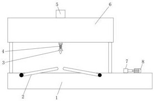
[0028] Both sides of the base 1 are provided with two sets of circular grooves, and a fixed mechanism 2 is connected to the circular grooves in rotation. The fixed mechanism 2 includes an L-shaped clamping rod 15, and the lower part of the vertical arm of the L-shaped clamping rod 15 The side close to the side wall of the base 1 is fixedly equipped with connecting ear pieces inserted in the circular groove on the base 1, and the lower part of the vertical arm of the L-shaped clamping rod 15 is provided with a threaded through hole pointing to the direction of the base 1. And a clamping screw 16 is connected to the internal thread of the threaded through hole. During use, the L-shaped clamping rod 15 is deflected so that its horizontal support arm is placed on the upper surface of the cast iron, and the clamping screw 16 is screwed in, thereby The L-shaped clamping rod 15 clamps and fixes the iron casting, which facilitates the subsequent drilling process;

Embodiment 2

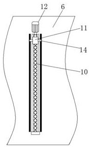
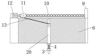
[0030] The adjustment mechanism 5 includes a fixed plate 9 and a second motor 12 fixedly installed on both sides of the bar-shaped opening on the top seat 6, and the output shaft of the second motor 12 is concentrically connected with a reciprocating lead screw 10 that is rotatably connected with the fixed plate 9. The outer threaded sleeve of the lead screw 10 is provided with a threaded sleeve 11, and both sides of the threaded sleeve 11 are fixedly equipped with L-shaped guide rods 14, and the top of the top seat 6 is provided with two sets of bar-shaped guides parallel to the reciprocating screw 10. Slot, the vertical support arm of L-shaped guide rod 14 is slidingly connected with top base 6 in the guide groove, and the bottom end of threaded sleeve 11 is connected with the deflection rod 13 inserted into the inside of the bar-shaped opening on top base 6. The seat 6 is provided with vertical guide grooves on both sides of the strip-shaped opening, and the telescopic rod 2...

Embodiment 3

[0035] One side of the top of the base 1 is provided with a collection tank, and the top of the base 1 is fixedly installed on both sides of the collection tank with a push rod motor 8 whose output shaft points to the horizontal direction, and one end of the output shaft of the push rod motor 8 is fixedly connected with an adsorption mechanism 7 The inside of the adsorption mechanism 7 is provided with an electromagnet.

[0036] After the iron castings are drilled, start the push rod motor 8 to make the adsorption mechanism 7 move horizontally, and energize the electromagnet inside the adsorption mechanism 7, and then absorb the iron filings scattered on the upper surface of the base 1. After completion, the adsorption mechanism 7 is returned to the upper side of the collection tank, and the electromagnet is powered off, so that the absorbed iron filings fall into the collection tank for collection.


PUM


Abstract

The invention relates to the technical field of iron casting machining, in particular to an engineering machinery iron casting drilling waste chip recycling device. The device comprises a base, a top seat is fixedly installed at the top end of the base through a supporting rod, a strip-shaped through hole is formed in the top seat in the vertical direction, and an adjusting mechanism is installed at the position, at the strip-shaped through hole, of the top end of the top seat. One end of the adjusting mechanism penetrates through the top seat at the strip-shaped through hole and is connected with a first motor, and an output shaft of the first motor is vertically downward and fixedly connected with a cutter fixing table. According to the waste chip recycling device, an iron casting can be well fixed and clamped in the treatment process, and then the iron casting can be conveniently drilled in cooperation with the cutter fixing table, the first motor and the adjusting mechanism; and chips generated in the drilling process of the iron casting can be effectively adsorbed and collected, so that the top surface of the base is cleaned, and the utilization efficiency of the iron casting is improved.

Description

technical field [0001] The invention relates to the technical field of iron castings processing, in particular to a device for recycling waste debris from drilling iron castings of engineering machinery. Background technique [0002] In the process of production and processing of iron castings, in order to ensure that iron castings can be used in subsequent production, iron castings are often treated to a certain extent, among which drilling treatment is one of the more common ones. However, iron castings will produce more iron filings during the drilling process. If these iron filings are not processed, on the one hand, they will affect the workbench and reduce the quality of the subsequent processed workpieces; on the other hand, it is easy to cause Waste of resources. For this reason, we propose a device for recovering waste debris from drilling of iron castings for engineering machinery. Contents of the invention [0003] The purpose of the present invention is to so...

Claims


Application Information

Patent Timeline
Patent Type & Authority Applications(China)
IPC IPC(8): B23B47/00B23Q3/06B23Q11/00
CPCB23B47/00B23Q3/06B23Q11/00B23Q11/0042
Inventor 周子钰周谊
Owner 射阳中路机械制造有限公司
Why Eureka
Try Eureka