

Clutch mechanism and transmission device of hole opening machine using clutch mechanism
A technology of clutch mechanism and transmission device, which is applied in the direction of transmission device, gear transmission device, transmission device control, etc., can solve the problems of personnel, equipment and even major accidents, and achieve the effect of saving gearbox space, simple structure and small volume
Inactive Publication Date: 2011-01-05
贾亮亮
View PDF0 Cites 0 Cited by
- Summary
- Abstract
- Description
- Claims
- Application Information
AI Technical Summary
Problems solved by technology
When the engagement or separation is realized, since the handle has no braking device, once the operator makes a wrong operation, it will cause personnel, equipment and even major accidents.
Method used
View moreImage
Smart ImageViewing Examples

Examples
Embodiment Construction
Login to View More PUM
 Abstract
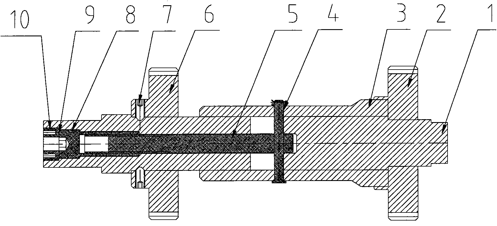
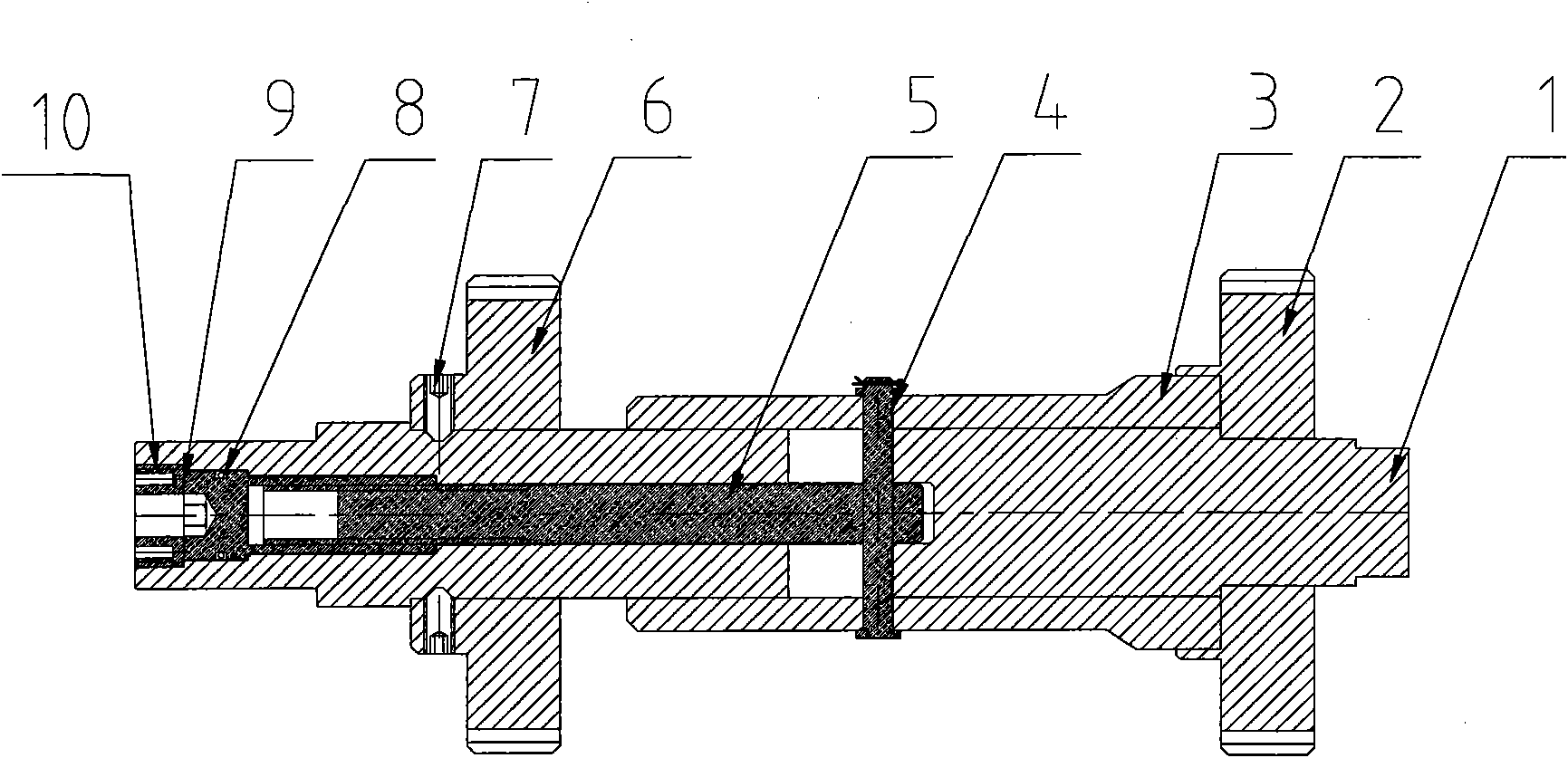
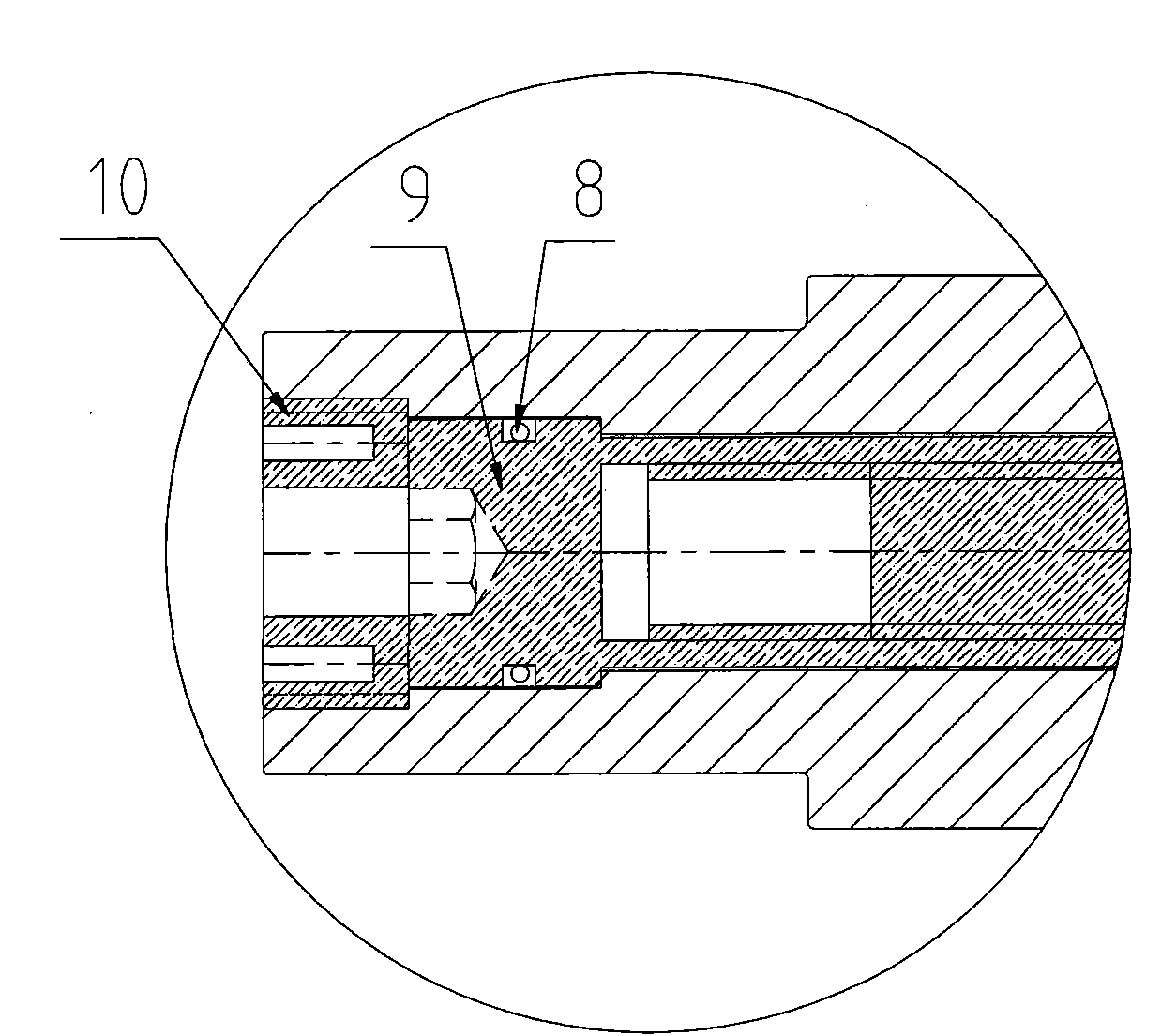
The invention discloses a clutch mechanism and a transmission device of a hole opening machine using the clutch mechanism. The clutch mechanism comprises a clutch sleeve, a clutch mechanism main shaft formed by a clutch mechanism driving section and a clutch mechanism driven section, a clutch mechanism driving gear, a clutch mechanism driven gear and a connecting component and the like. The invention can be used in the transmission device of the hole opening machine; the periphery of a transmission shaft of the transmission device is provided with one or more clutch mechanisms; by operating the clutch mechanism, the clutch mechanism driven gear of each clutch mechanism is meshed with one corresponding driven gear on the transmission shaft; and the clutch mechanism driving gear on the clutch mechanism is meshed with the driving gear sleeved on the transmission shaft. The clutch mechanism has accurate position for clutch switching, safety and reliability. When being applied in the hole opening machine, the invention can easily realize multigear variable transmission feeding, avoid misoperation accident, is safe, reliable and durable and has low cost.
Description
A clutch mechanism and a drilling machine transmission device using the clutch mechanism 【Technical field】 The invention relates to the technical field of pipeline emergency repair, maintenance and maintenance equipment, in particular to a clutch mechanism and a drilling machine transmission device using the clutch mechanism. 【Background technique】 With the rapid development of energy production in my country and even in the world, pipelines are playing an increasingly important role in energy transmission. However, no matter what kind of material is used to construct the pipeline, after several years of construction, the existence of force majeure factors such as settlement, corrosion, and external construction may cause the pipeline to be damaged during operation, requiring pipeline maintenance and overhaul. And with the development of national urban planning and construction, the existing pipeline reconstruction project is also imperative. At present, for the maintenan...
Claims
Login to View More Application Information
Patent Timeline
 Patent Type & AuthorityPatents(China)
IPC IPC(8): F16D23/00F16H3/08F16H63/30F16L55/16
Inventor贾亮亮
Owner贾亮亮