Light guide plate and back light module

A technology of light guide plate and light emitting surface, applied in the direction of light guide, optics, optical components, etc., can solve the problems such as the inability to achieve large bending, large brightness loss, and the inability to apply large-sized BLU to the light guide plate.

Inactive Publication Date: 2010-09-01
AU OPTRONICS (XIAMEN) CORP +1
View PDF0 Cites 6 Cited by
  • Summary
  • Abstract
  • Description
  • Claims
  • Application Information

AI Technical Summary

Problems solved by technology

However, due to technical limitations, this kind of integrated flexible light guide plate cannot be applied t

Method used


Image

  • Light guide plate and back light module
  • Light guide plate and back light module
  • Light guide plate and back light module

Examples


Embodiment Construction

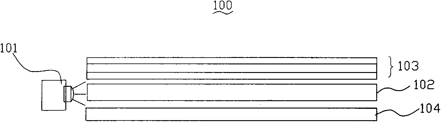
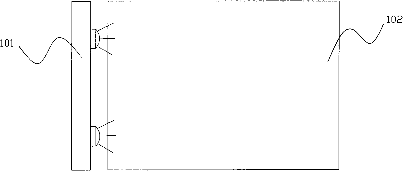
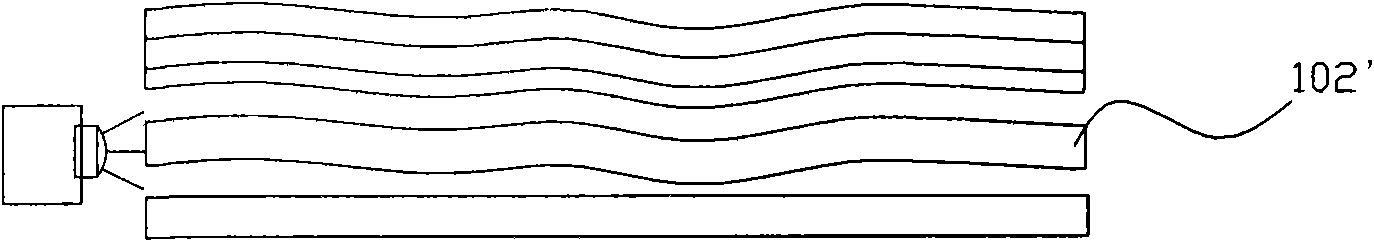
[0028] See Figure 2A-2B , Figure 2A is a top view of the backlight module of the present invention, Figure 2B yes Figure 2A Sectional view of line AA. As shown in the figure, the backlight module 200 has a light source device 210 and a combined light guide plate 220 . Wherein the light source device may be a light bar (Light Bar) composed of a plurality of LEDs, or a light emitting device such as a single fluorescent tube, which is located on one side of the light guide plate 220; the light guide plate 220 is composed of a plurality of sub-light guide plates 221 Each of the light guide plates has a hinge structure for connection, so that the light guide plate 220 can be bent as a whole, such as Figure 2B shown in . The combined light guide plate of the present invention will be described below in conjunction with specific embodiments.

[0029] Please also see Figure 3A with Figure 3B , Figure 3A It is a structural schematic diagram of the first embodiment of t...


PUM


Abstract

The invention provides a light guide plate and a back light module using the same. The light guide plate is formed by the connection of multiple sub-light guide plates by hinge structures, wherein the contact surface of each sub-light guide plate is designed into a concave-convex matching cambered surface structure to enable the whole light guide plate to be bent to a certain extent along the cambered surfaces. Therefore, the light guide plate and the back light module have the advantage of large bending amplitude and are not influenced by the dimension.

Description

technical field [0001] The invention relates to a light guide plate and a backlight module with the light guide plate, in particular to a combined light guide plate and the backlight module with the light guide plate. Background technique [0002] With the development of digital technology, liquid crystal display products have been widely used in various aspects of daily life, and the quality requirements for liquid crystal display (Liquid Crystal Display, LCD) screens are gradually increasing. However, the liquid crystal itself does not emit light, and a light source needs to continuously provide light to enter the display screen to realize image display. In liquid crystal display products, a backlight module is usually selected to provide light. [0003] Such as Figures 1A-1B as shown, Figure 1A It is a schematic side view structure of an existing backlight module, Figure 1B yes Figure 1A A schematic top view of the backlight module shown. The backlight module (Bac...

Claims


Application Information

Patent Timeline
IPC IPC(8): F21V8/00G02F1/13357
Inventor 钟辉林叶云林永清
Owner AU OPTRONICS (XIAMEN) CORP
Why Eureka
Try Eureka