Accumulator

A technology of accumulator and bellows, applied in the direction of accumulator device, actuator accumulator, fluid pressure actuating device, etc., can solve the problem of inability to ensure the expansion and contraction stroke of the bellows, achieve smooth relative movement and improve durability Effect

Active Publication Date: 2010-09-01
EAGLE INDS
View PDF8 Cites 18 Cited by
  • Summary
  • Abstract
  • Description
  • Claims
  • Application Information

AI Technical Summary

Problems solved by technology

[0013] (ハ) When the zero falls, the bellows shrinks when the auxiliary bellows is extended, and the bellows stop shrinking when the auxiliary piston reaches the bottom, so a sufficient bellows telescopic stroke cannot be ensured

Method used


Image

  • Accumulator
  • Accumulator
  • Accumulator

Examples


Embodiment

[0077] Embodiments of the present invention will be described below with reference to the drawings.

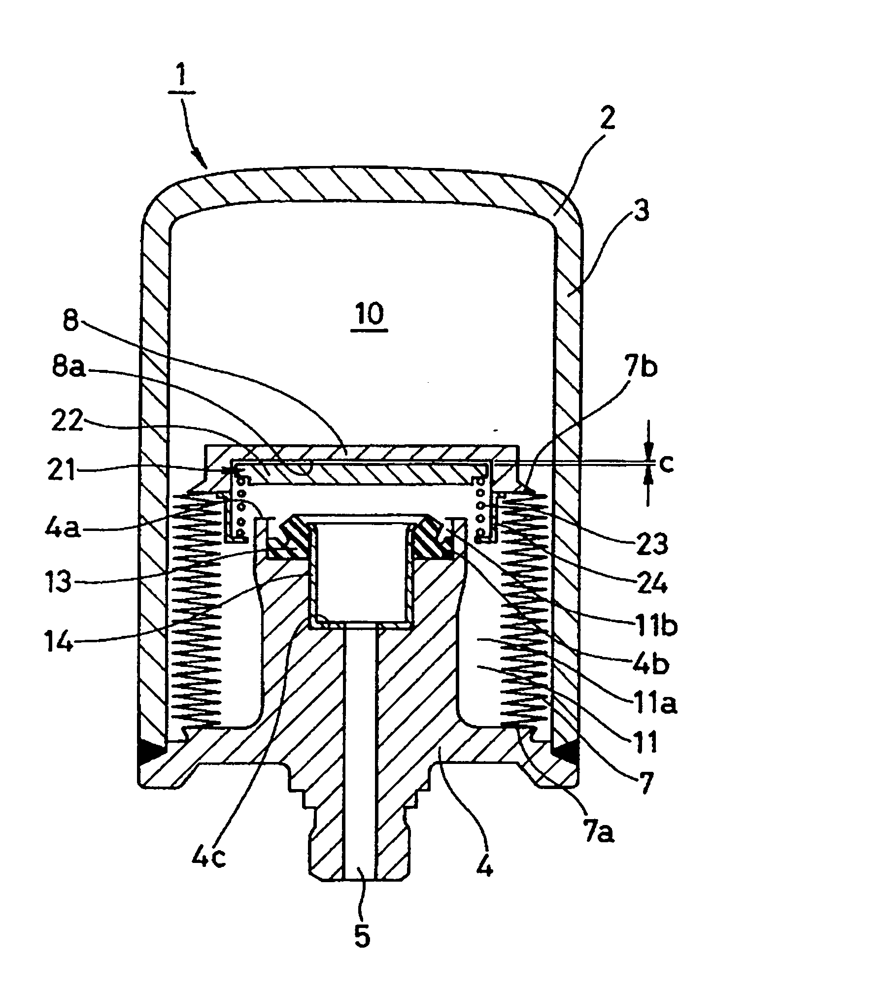
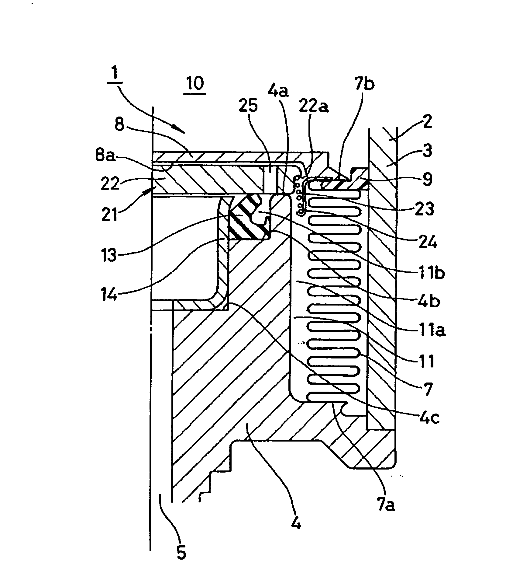
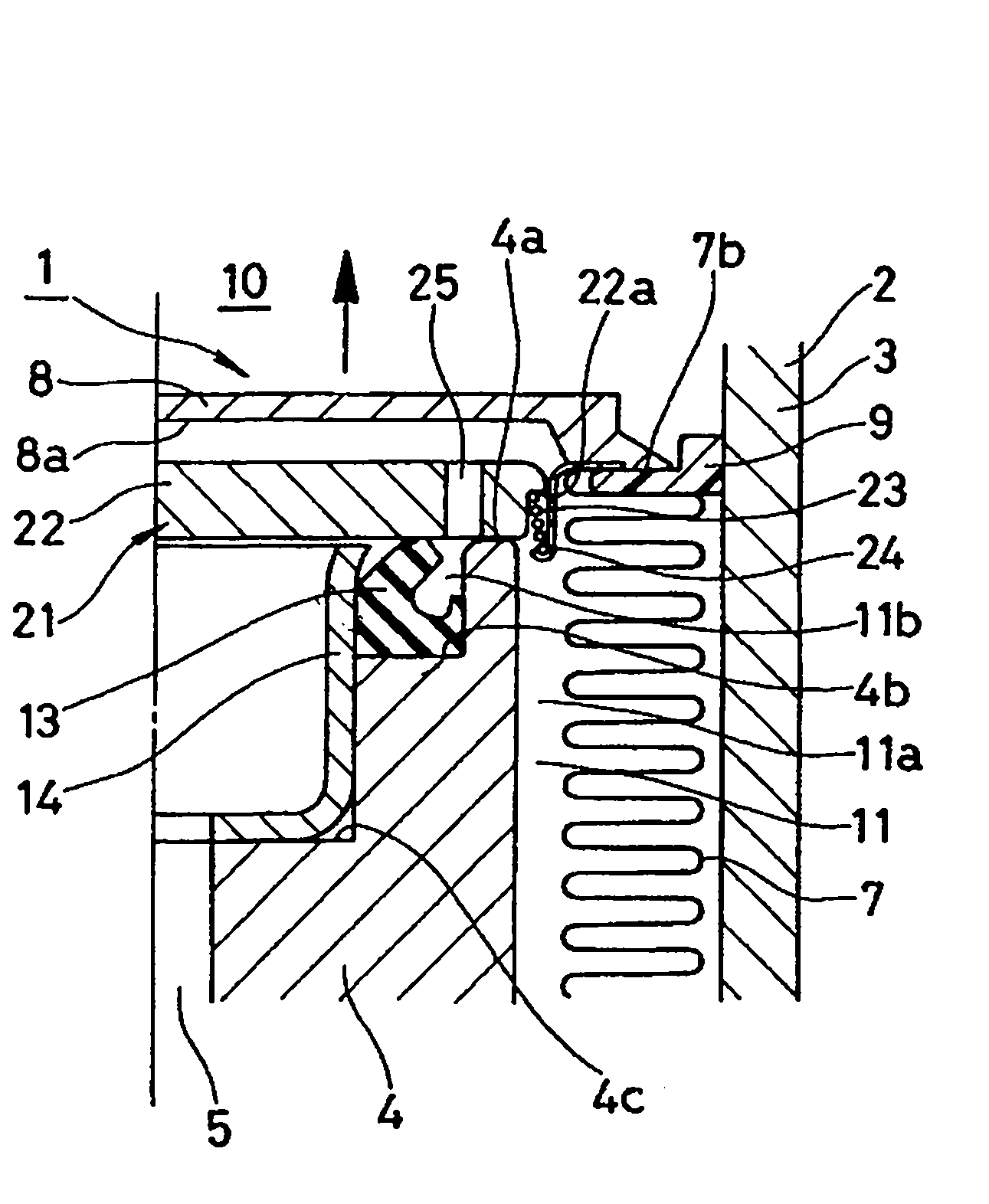
[0078] Figure 1 to Figure 3 A full cross-section and a partial cross-section of the accumulator 1 according to the embodiment of the invention are shown. figure 1 , figure 2 , image 3 The states during normal operation, zero drop, and thermal expansion in the zero drop state are shown, respectively.

[0079] The accumulator 1 of the present embodiment is a metal bellows type accumulator using a metal bellows as the bellows 7, and is configured as follows.

[0080] That is, first, an accumulator case 2 having an oil passage 4 connected to a pressure pipe (not shown) is provided, and a bellows 7 is arranged inside the case 2 to separate the inner space of the case 2 into a gas chamber in which high-pressure gas is enclosed. The chamber 10 communicates with the liquid chamber 11 of the passage hole 5 of the oil passage 4 . The casing 2 is formed by combining a bottomed c...


PUM


Abstract

An outside gas type accumulator has a mechanism for reducing the pressure difference occurring when liquid confined in a liquid chamber and gas filling the liquid chamber in zero-down state expand thermally, and restrains abnormal deformation of a bellows by reducing the pressure difference between the inside and outside of the bellows. A pressure difference regulation mechanism (21) reduces the pressure difference occurring when liquid confined in the liquid chamber (11) and gas filling the liquid chamber in the zero-down state expand thermally. The regulation mechanism (21) has a movable plate (22) supported by a coil spring (23) on the oil port (4) side of a bellows cap (8). During normal operation, the plate (22) moves together with the cap (8) by being supported by the spring (23), and the plate (22) moves together with the cap (8) and to be brought into contact with a seal (13) in the zero-down state. When the liquid and the filling gas expand thermally, the plate (22) maintains contact with the seal (13), and the cap (8) moves up to a position where the liquid pressure and the gas pressure are balanced while compressing the spring (23).

Description

technical field [0001] The present invention relates to an accumulator used as a pressure storage device or a pulse pressure attenuation device. The accumulator of the present invention is used, for example, in hydraulic lines and the like in vehicles such as automobiles. Background technique [0002] Previously, there has been known an accumulator in which bellows are arranged inside an accumulator housing having an oil passage connected to a pressure pipe, and the inner space of the housing is partitioned into an air chamber enclosing high-pressure gas With the liquid chamber communicating with the passage hole, in this accumulator, as its type, has the following types: as Image 6 As shown, by fixing the other end (fixed end) 51b of the bellows 51 with the bellows cover 52 on one end (moving end) 51a to the end cover 54 on the top of the casing 53, the inner peripheral side of the bellows 51 becomes the air chamber 55, and the outer peripheral side Become a liquid chambe...

Claims


Application Information

Patent Timeline
Patent Type & Authority Applications(China)
IPC IPC(8): F15B1/08
CPCF15B2201/3153F15B2201/205F15B2211/32F15B2201/411F15B1/103
Inventor 中冈真哉三宅邦明斋藤知成二家本博之水谷英二小仓智男
Owner EAGLE INDS
Why Eureka
Try Eureka