Bottle conveying device of bottle blowing machine

A bottle blowing machine and bottle conveying technology, which is applied in the field of blow molding machines, can solve problems such as poor stability, complex structure, easy bottle jamming, etc., and achieve the effect of solving docking problems, moving smoothly, and running reliably

Active Publication Date: 2012-08-29
JIANGSU NEWAMSTAR PACKAGING MACHINERY
View PDF7 Cites 1 Cited by
  • Summary
  • Abstract
  • Description
  • Claims
  • Application Information

AI Technical Summary

Problems solved by technology

However, the structure of this device is complicated, and it is easy to jam the bottle and has poor stability.
Therefore, it is currently seldom used

Method used


Image

  • Bottle conveying device of bottle blowing machine
  • Bottle conveying device of bottle blowing machine
  • Bottle conveying device of bottle blowing machine

Examples


Embodiment Construction

[0012] Specific embodiments of the present invention will be described in detail below with reference to the accompanying drawings.

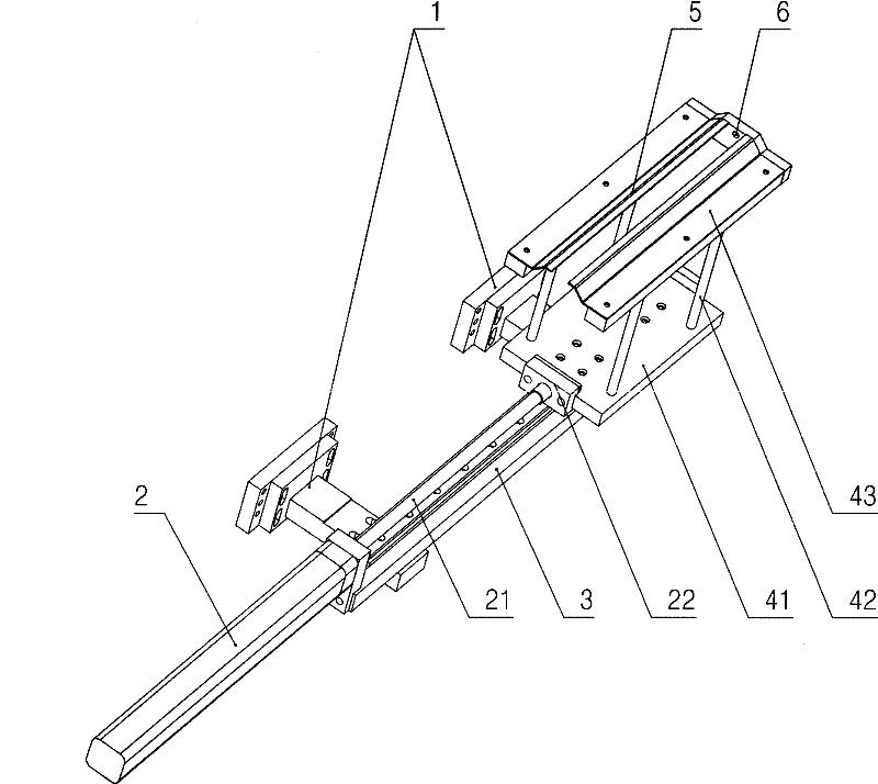
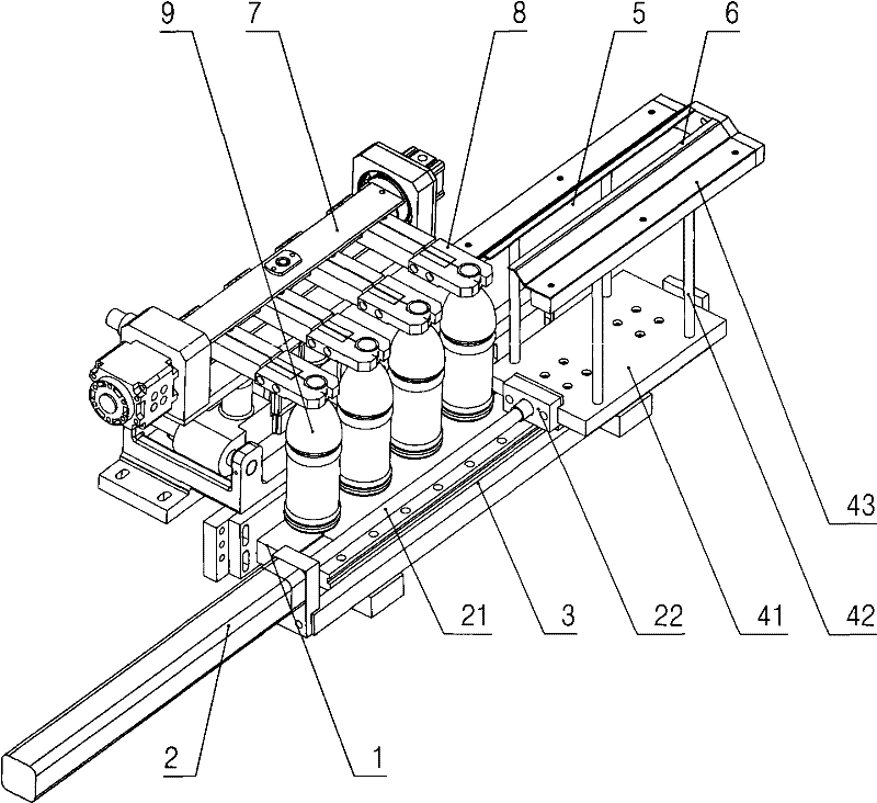
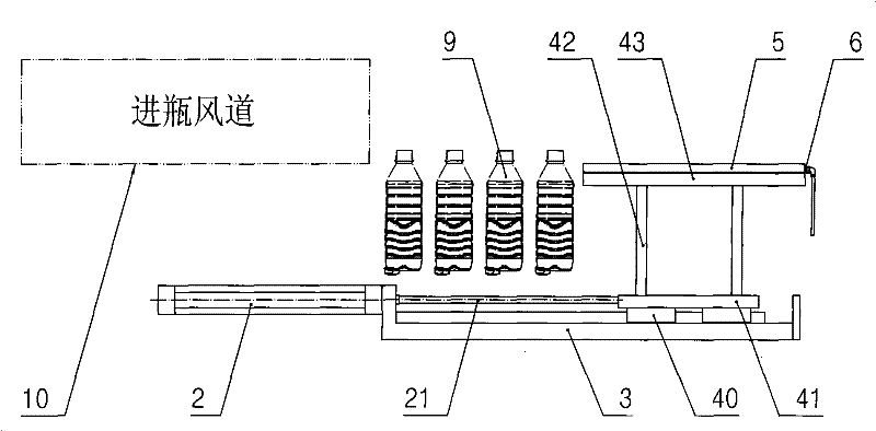
[0013] like figure 1 As shown, the bottle conveying device of the bottle blowing machine according to the present invention includes: a pair of support bases 1 installed on the bottle blowing machine, the pair of support bases 1 is provided with a slide rail 3, and one end of the slide rail 3 is provided with a The cylinder 2 and the sliding rail 3 are provided with a sliding frame, and the sliding frame includes: a base 41, and the base 41 is set on the sliding rail 3 through the movable slider 40 at the bottom of the base 41 - see Figure 3 to Figure 6 As shown, two sides of the base 41 are respectively provided with a pair of uprights 42, the ends of each pair of uprights 42 are provided with a mounting seat 43, the inner side of the pair of mounting seats 43 is respectively provided with a bottle hanging bar 5, and the pair of hanging The i...


PUM


Abstract

The invention discloses a bottle conveying device of a bottle blowing machine which has simple structure, stability and reliability. The bottle conveying device comprises a supporting seat, the supporting seat is provided with a slide track; one end of the slide track is provided with an air cylinder; the slide track is provided with a sliding rack; a piston rod of the air cylinder is connected with the sliding rack; and the sliding rack is provided with a pair of bottle hanging strips matched with bottlenecks to be clamped and compressed air nozzles matched with the pair of bottle hanging strips. The invention has very simple structure and very convenient daily maintenance; and the movement of the sliding rack is very stable on the slide track so that the operation of the integral bottleconveying device is very reliable, therefore the problem of the abutting joint of the linear type bottle blowing machine and a filling system is well solved. The bottle conveying device can be arranged on various bottle blowing machines.

Description

technical field [0001] The invention relates to a bottle blowing machine, in particular to a bottle conveying device of the bottle blowing machine. Background technique [0002] Polyester (PET) bottles must be arranged according to certain rules when entering the filling system, and the bottles blown out by the current linear blow molding machine are clamped and turned 180° by the bottle-out manipulator, and then the manipulator is released. The bottle is dropped into a container, where the bottle is cluttered and unable to interface directly with the filling system. [0003] In response to this problem, there are currently two traditional methods: the first method is to manually queue the bottles and send them to the filling system for filling; The belt feeds the bottles to the unscrambler for queuing, and then to the filling system for filling. Both of these methods can lead to secondary contamination of the bottle. [0004] Of course, there is also a bottle feeding dev...

Claims


Application Information

Patent Timeline
Patent Type & Authority Patents(China)
IPC IPC(8): B29C49/42B67C3/24B29L22/00
Inventor 杨新良董海龙陈中云
Owner JIANGSU NEWAMSTAR PACKAGING MACHINERY
Why Eureka
Try Eureka