Roof frame installation structure and car comprising same

A technology for installing structures and roofs, which is applied to the upper structure, upper structure sub-assembly, vehicle parts, etc., can solve the problems of large deformation of the upper part of the car body, threat to the life safety of the occupants, deformation of the roof frame, etc. Effects of vibration, ride comfort improvement, and strength improvement

Inactive Publication Date: 2010-09-08
BEIQI FOTON MOTOR CO LTD
View PDF5 Cites 8 Cited by
  • Summary
  • Abstract
  • Description
  • Claims
  • Application Information

AI Technical Summary

Problems solved by technology

[0003] However, there are two major disadvantages in the traditional mounting structure of the roof frame: first, although the traditional mounting structure can basically guarantee the supporting effect on the roof frame during the normal running of the car, when the car rolls over, The top of the car, especially the roof frame, is often directly impacted by the ground (especially the ground protrusions), so the deformation of the upper part of the car body will be large, which often causes the roof frame to deform severely to the inside of the car, and thus causes the roof to be damaged. The frame and its beams intrude into the interior space of the car where the occupants are located. This will cause the occupants to collide with the intruded roof frame and its beams when the car rolls over and the occupants seriously lose their balance. Injure or even kill the passengers, seriously threatening the safety of the occupants; second, the traditional roof installation structure is essentially a rigid connection structure
Since the connection between the roof frame and the side frame is rigid, it cannot absorb vibrations, and the side frame is rigidly connected to the floor frame or the frame, so the roof frame will repeatedly pull and compress the side frame Skeleton, this pulling force and compression force will be converted into rapid and severe micro-vibration of the side frame, which will cause the side window glass installed on the car side frame to vibrate sharply, affecting the ride comfort of the car

Method used


Image

  • Roof frame installation structure and car comprising same
  • Roof frame installation structure and car comprising same
  • Roof frame installation structure and car comprising same

Examples


Embodiment Construction

[0030] Specific embodiments of the present invention will be described in detail below with reference to the accompanying drawings.

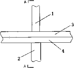
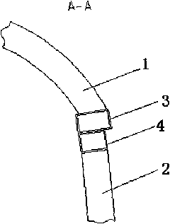
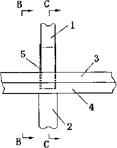
[0031] The car roof frame is generally a frame structure composed of rectangular pipe beams. The beams on both sides of the roof frame are called roof side beams 3, and the roof side beams 3 are respectively fixed to the left and right sides by welding. The side wall of the framework is on the upper stringer 4. A plurality of roof beams 1 parallel to each other are fixed between the roof side beams 3 on both sides of the roof frame along the longitudinal direction of the vehicle. Typically, each roof beam 1 is located at 2 side columns corresponding to the side frame. In the same cross-section of the car (the lower section of the side wall column 2 is fixed to the corresponding beam of the car floor frame), thereby forming a plurality of closed stress rings in multiple cross-sections of the car perpendicular to the longitudinal direction of the ...


PUM


Abstract

The invention relates to a roof frame installation structure. A roof side rail (3) of the roof frame is fixed on a side wall roof rail (4) of a side wall frame along the longitudinal direction of the car, wherein the roof frame installation structure also comprises a support member (5), the support member (5) is fixed on the side wall roof rail (4) and a roof cross rail (1) of the roof frame from the inner part of the car, and the support member and the roof cross rail (1) are located in the same cross section of the car. The technical scheme of the invention can obviously increase the rigidity and the strength of the upper structure of a body frame, so that the roof frame of the car can be prevented from seriously deforming toward the inner part of the car when a side turnover accident occurs to the car so as to ensure the safety of passengers.

Description

technical field [0001] The invention relates to an automobile roof frame installation structure. In addition, the present invention also relates to an automobile comprising the roof frame installation structure. Background technique [0002] Automobile (such as passenger cars, commercial vehicles, etc.) skeletons generally include front wall frames, rear wall frames, left and right side wall frames, floor frames, and roof frames. Among them, the traditional installation structure of the roof frame is as follows: figure 1 and figure 2 As shown, the roof beam 1 of the roof frame is connected to the roof side beam 3, and the roof side beam 3 is further welded to the side wall upper longitudinal beam 4 of the side wall frame along the longitudinal direction of the vehicle. In order to improve the supporting effect of the side frame on the roof frame, the roof beam 1 of the roof frame and the corresponding side column 2 of the side frame are generally in the same cross sectio...

Claims


Application Information

Patent Timeline
Patent Type & Authority Applications(China)
IPC IPC(8): B62D25/06
CPCB62D25/06
Inventor 赵天红周骏
Owner BEIQI FOTON MOTOR CO LTD
Why Eureka
Try Eureka