Constant speed device for tandem vibratory roller

A technology of vibratory road roller and constant speed device, which is applied in the field of construction machinery, can solve the problem of operator fatigue and boredom, and it is difficult to move forward or backward. requirements and other issues, to achieve the effect of simple operation, practical operation and meeting speed requirements

Inactive Publication Date: 2010-09-08
柳工无锡路面机械有限公司
View PDF6 Cites 4 Cited by
  • Summary
  • Abstract
  • Description
  • Claims
  • Application Information

AI Technical Summary

Problems solved by technology

In the several forward or backward speed control operations of the double drum vibratory roller, it is difficult to achieve the same forward or backward driving speed each time; such repetitive work not only makes the operator feel tired and bored easily, but also makes the speed control uncertain. It also makes the compaction effect of the double-drum vibratory roller not meet the requirements

Method used


Image

  • Constant speed device for tandem vibratory roller
  • Constant speed device for tandem vibratory roller

Examples


Embodiment Construction

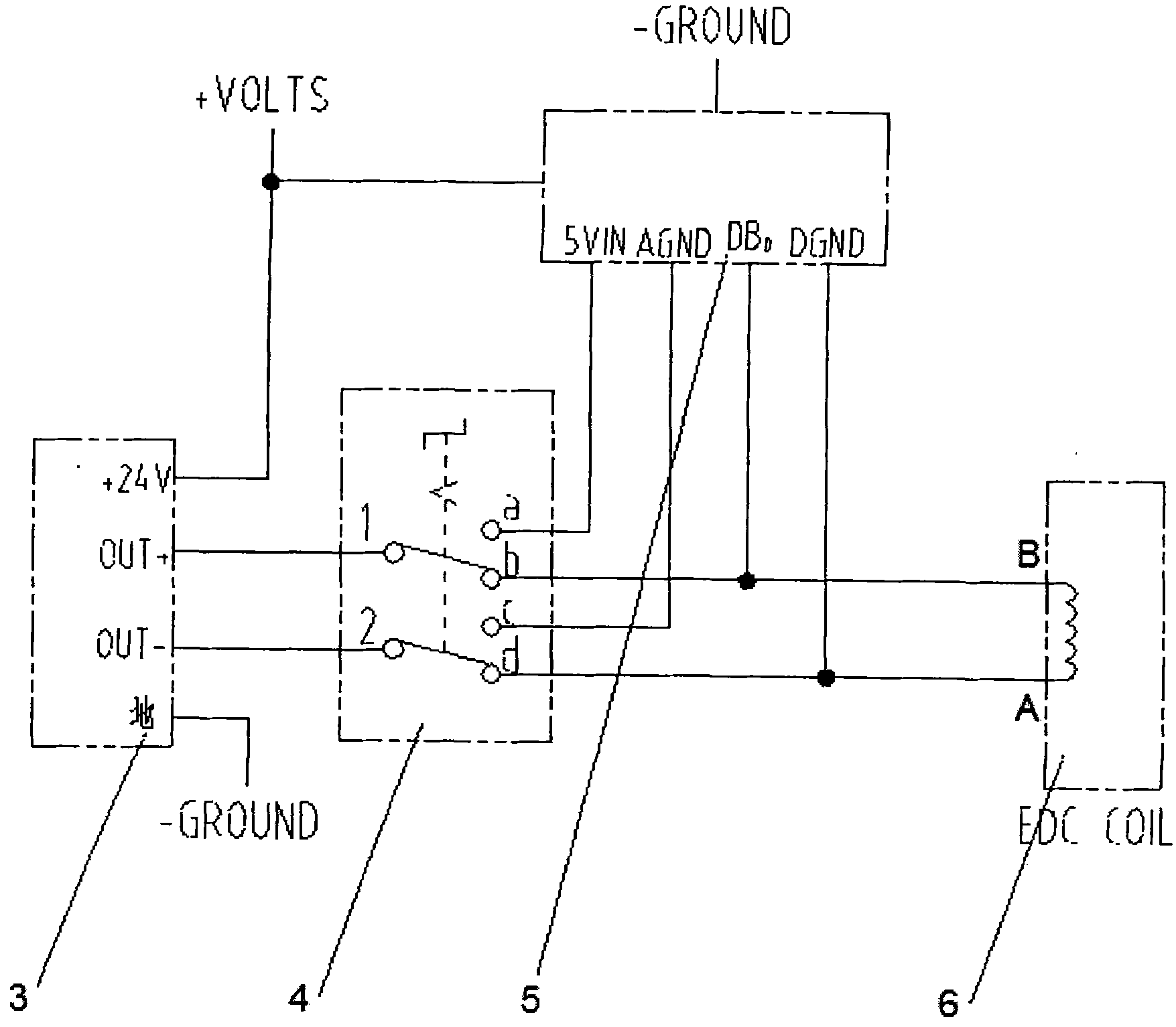
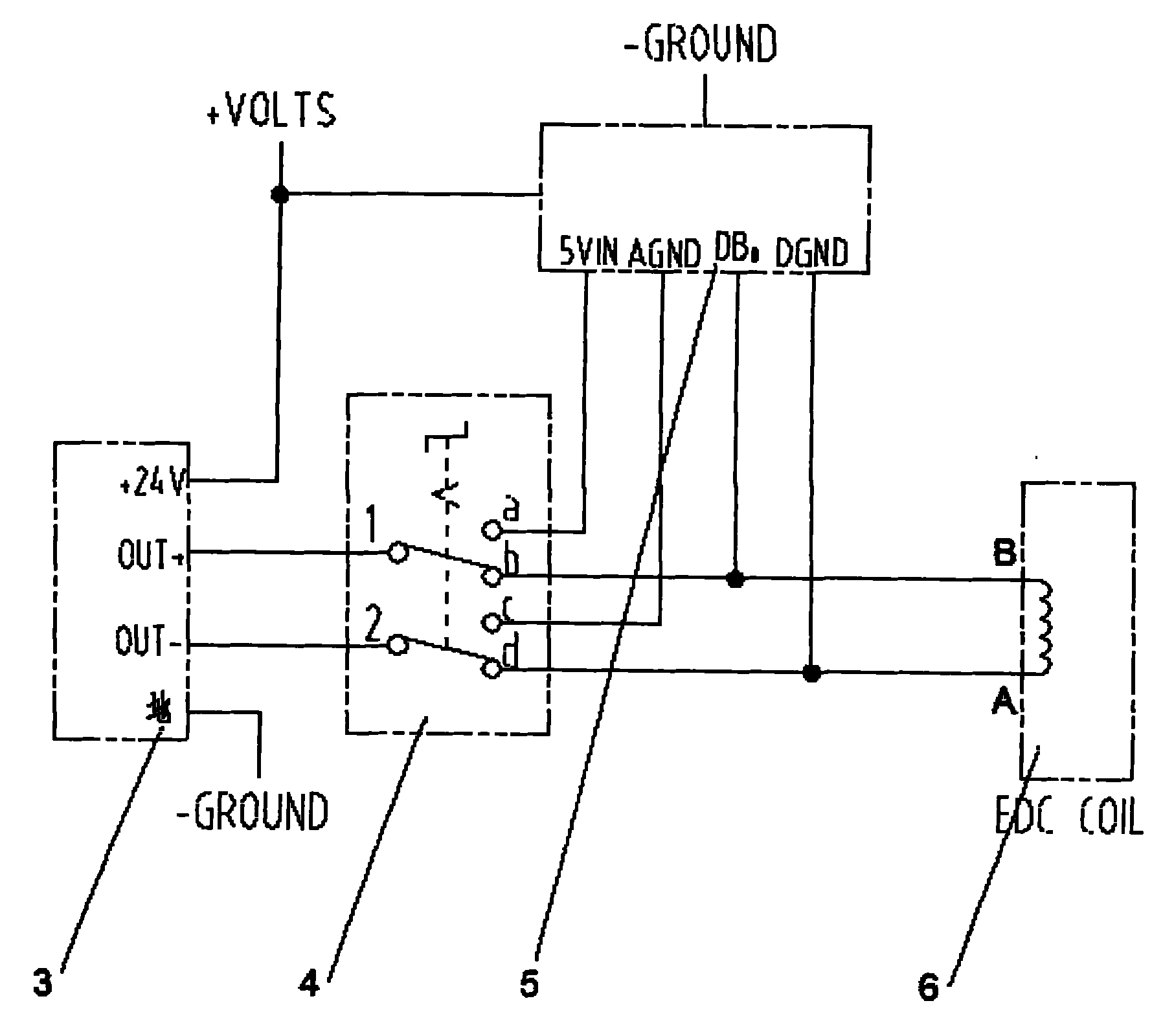
[0011] see figure 1 , figure 1 It is the principle block diagram of the constant speed device of the double steel wheel vibratory road roller of the present invention. Depend on figure 1 It can be seen that the speed-fixing device of the double-steel-wheel vibratory roller of the present invention includes a variable-speed control handle 3 and an A / D conversion circuit 5, and is characterized in that it adds a constant-speed mode on the control panel of the double-drum vibratory roller. Switch 4, the constant speed mode switch 4 has two normally closed contacts 1-b, 2-d and two normally open contacts 1-a, 2-c, the two inputs of the constant speed mode switch 4 Terminals 1 and 2 are connected to the OUT+ and OUT- terminals of the shift control handle 3 respectively. At the output end of the constant speed mode changeover switch 4, the two normally closed ports b and d of the constant speed mode changeover switch 4 are respectively connected with the two ends of the coils A a...


PUM


Abstract

The invention relates to a constant speed device for a tandem vibratory roller, comprising a shift control handle (3) and an A / D conversion circuit (5). In the device, a control panel of the tandem vibratory roller is provided with a constant speed mode switch (4), wherein the constant speed mode switch (4) is provided with two normally closed contacts and two normally open contacts; two input ends of the constant-speed mode switch (4) are connected with the OUT+ end and the OUT- end of the shift control handle (3); two normally closed ports (b, d) of the constant speed mode switch (4) are connected with two ends of the coil of the proportional electromagnetic valve on a running variable pump (6) respectively; two normally open ports (a, c) of the constant speed mode switch (4) are connected with 5VIN and AGND of the A / D conversion circuit (5) respectively; and two output ports of the A / D conversion circuit (5) are connected with two ends of the coil of the proportional electromagnetic valve on the running variable pump (6) respectively. The device can realize the phenomenon of same running speed in each forward moving or withdrawing, and reduce working intensity of an operator.

Description

(1) Technical field [0001] The invention relates to a vibratory road roller, in particular to a constant speed device of a double steel wheel vibratory road roller. It belongs to the technical field of engineering machinery. (2) Background technology [0002] The compaction theory requires that when the double-steel-wheel vibratory roller works, the interval between impacts on the ground is not greater than 3cm, which is equivalent to the rolling speed of the double-drum vibratory roller when it is working at 2.7-5.4km / h. At present, when the traditional double-drum vibratory roller is working, the operator needs to repeatedly push, pull and adjust the travel control handle to make the double-drum vibratory roller reciprocate continuously on the asphalt road within a certain speed range. In the several forward or backward speed control operations of the double drum vibratory roller, it is difficult to achieve the same forward or backward driving speed each time; such repeti...

Claims


Application Information

Patent Timeline
Patent Type & Authority Applications(China)
IPC IPC(8): E01C19/28
Inventor 黄宁波董程炜郭启华谈鸿雁丁赛杰申运利
Owner 柳工无锡路面机械有限公司
Why Eureka
Try Eureka