Optical testing device

A technology for optical testing and robotic arms, applied in the field of optical testing, can solve the problems of low efficiency, time-consuming, and wear of mechanical connection parts of the lens control module, and achieve the effect of reducing the number of times, reducing the testing time, and improving the testing efficiency.

Inactive Publication Date: 2010-09-08
BOE TECH GRP CO LTD +1
View PDF0 Cites 6 Cited by
  • Summary
  • Abstract
  • Description
  • Claims
  • Application Information

AI Technical Summary

Problems solved by technology

[0003] The optical testing device in the prior art has the following problems: due to the need to obtain the optical parameters of multiple viewing angles of the sample to be tested, it is necessary to obtain the required viewing angle by moving the lens, and it takes time to move the lens every time, and the efficiency is not good. High, and multiple movements, resulting in the wear and tear of the various mechanical connection parts of the lens control module

Method used


Image

  • Optical testing device
  • Optical testing device
  • Optical testing device

Examples


Embodiment Construction

[0025] The technical solutions of the present invention will be described in further detail below with reference to the accompanying drawings and embodiments.

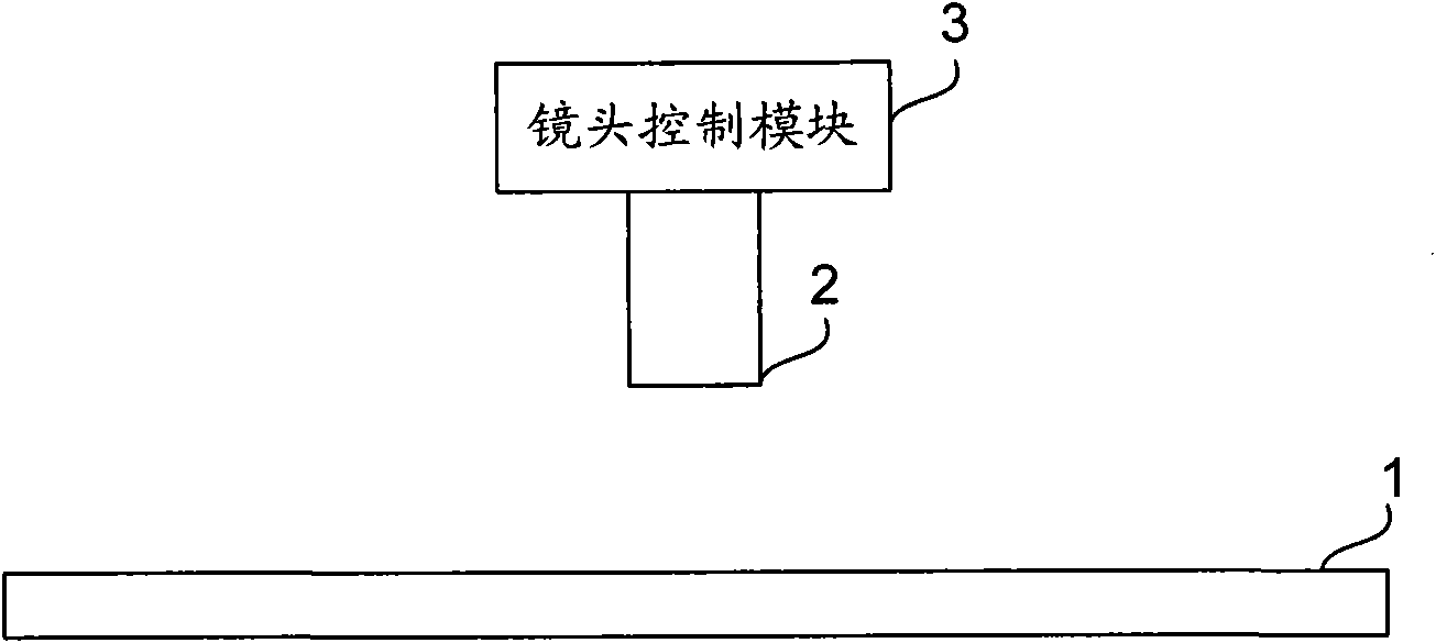
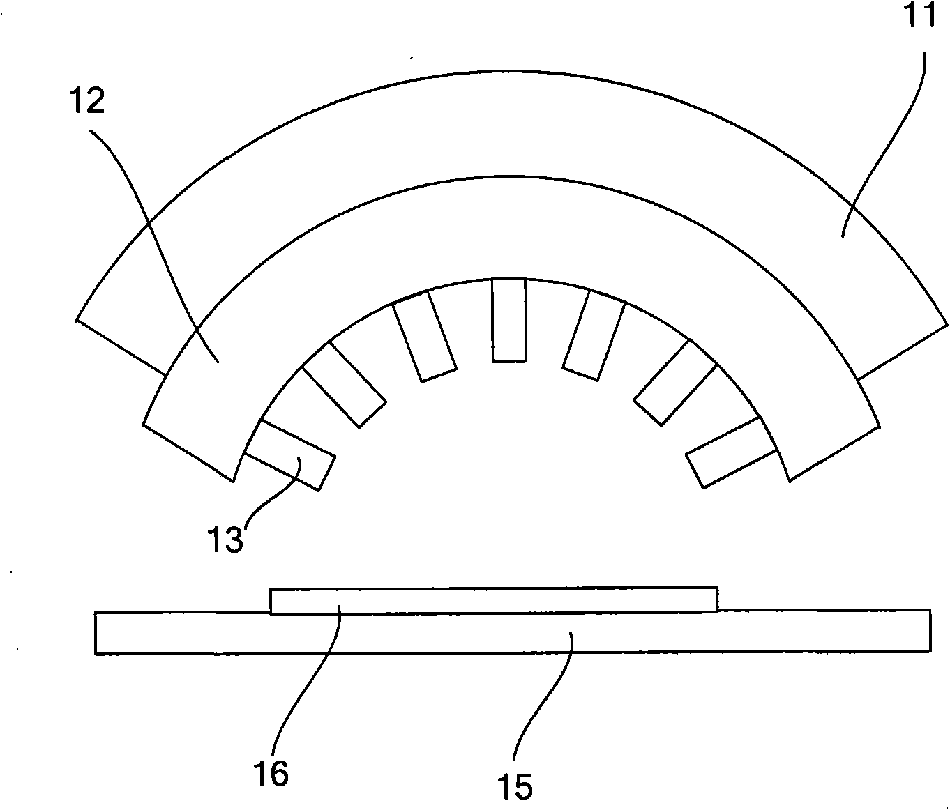
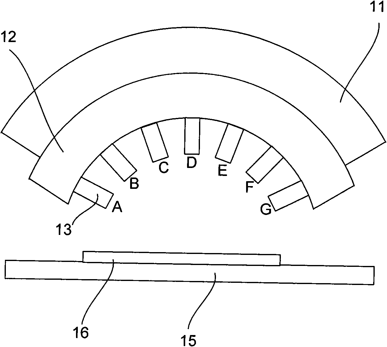
[0026] figure 2 It is a structural schematic diagram of the first embodiment of the optical testing device of the present invention, such as figure 2 As shown, the main structure of the optical testing device of the present embodiment includes a ring guide rail 11 and a ring robot arm 12. 12 is provided with a plurality of lenses 13, and the plurality of lenses 13 are used to test the optical parameters of the sample 16 placed on the base 15 to be tested. In the above technical solution of this embodiment, in order to obtain the optical parameters of the required viewing angle, the ring-shaped mechanical arm 12 is a circular shape with the sample 16 as the center of the circle, and the center angle corresponding to the ring-shaped mechanical arm 12 can be 0°-180°. Preferably, the central angle is 120°-150°. Corres...


PUM

PropertyMeasurementUnit
angleaaaaaaaaaa
angleaaaaaaaaaa

Abstract

The invention discloses an optical testing device comprising a base station for bearing samples to be tested, lenses for carrying out optical parameter test on the samples to be tested and an annular mechanism arm for bearing the plurality of lenses, wherein the annular mechanical arm is slidably arranged on an annular guile rail. During testing, by slidably arranging the annular mechanism arm on the annular guile rail and arranging the plurality of lenses on the annular mechanism arm, the synchronous regulation on visual angles of the plurality of lenses can be realized through sliding the annular mechanical arm on the annular guide rail, and test on the same testing region from different visual angles with the same time can be realized by batch treatment on relevant angles, thereby reducing the test time, improving the test efficiency, and reducing the abrasion of mechanical connecting pieces of the optical testing device due to the reduction of the times of movement of the lenses.

Description

technical field [0001] The invention relates to optical test technology, in particular to an optical test device for testing optical parameters of liquid crystal display (LCD) panels and other devices. Background technique [0002] figure 1 Shown is a schematic structural diagram of an optical testing device in the prior art, which is used for testing optical parameters of devices such as LCD panels, such as light transmittance, spectrum, light intensity and other parameters. like figure 1 As shown, the prior art optical testing device includes: a base 1 , a lens 2 and a lens control module 3 , the base 1 is used to carry the sample to be tested, and the lens control module 3 controls the lens 2 to move. During the test, the sample to be tested is placed on the base 1, and the lens control module 3 controls the movement of the lens 2, so as to obtain the optical parameters of the sample to be tested at different viewing angles. [0003] The optical testing device in the p...

Claims


Application Information

Patent Timeline
Patent Type & Authority Applications(China)
IPC IPC(8): G02F1/13G01M11/00
Inventor 吴昊黄婕妤于洪俊
Owner BOE TECH GRP CO LTD
Why Eureka
Try Eureka