
Novel pay-off frame of numerical-control winding machine

A technology of numerical control winding machine and pay-off frame, which is used in electromechanical devices, coil manufacturing, and motor-generator manufacturing, etc., can solve the problems of wire waste, incomplete wire release, and wire slack.

Inactive Publication Date: 2010-09-15
尹克善
View PDF0 Cites 11 Cited by
  • Summary
  • Abstract
  • Description
  • Claims
  • Application Information

AI Technical Summary

Problems solved by technology

[0003] The purpose of the present invention is to: provide a new type of CNC winding machine pay-off stand, to overcome the defects of wire rods that cannot be completely discharged due to structural reasons in the existing CNC winding machine pay-off stand, resulting in waste of wire rods; and In order to overcome the winding machine in the work, if it encounters an intermediate stop, the pay-off mechanism cannot stop in time. Under the action of inertial force, it will often continue to rotate for a certain distance, causing the wire to relax, and it is easy to cause discharge after restarting the machine. Irregular Line Defects

Method used


Image

  • Novel pay-off frame of numerical-control winding machine
  • Novel pay-off frame of numerical-control winding machine
  • Novel pay-off frame of numerical-control winding machine

Examples


Embodiment Construction

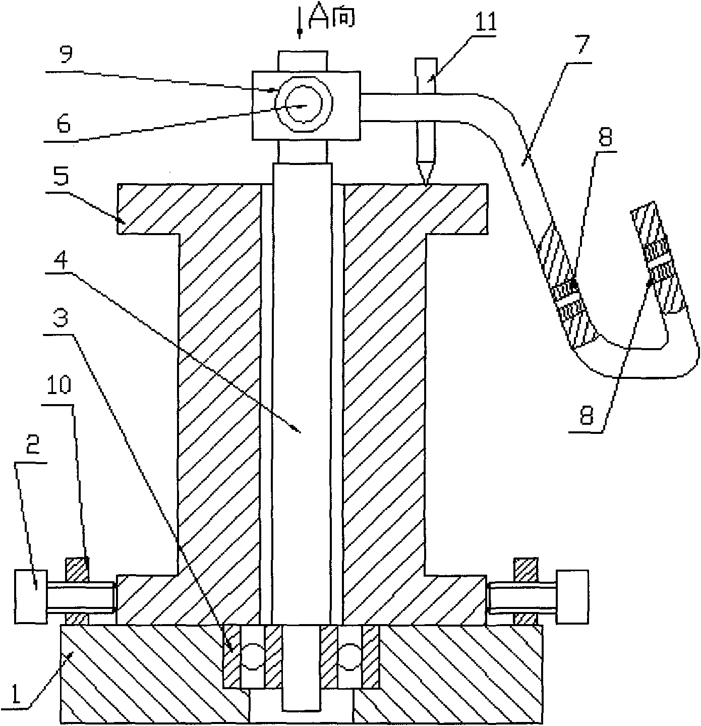
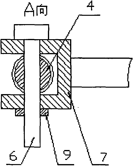
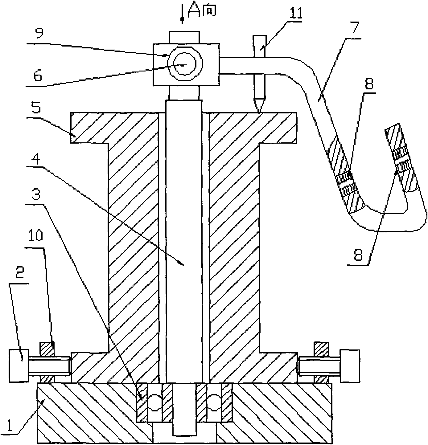
[0010] On the upper plane of the base (1) near the edge of the circumference, an appropriate number of positioning screw seats (10) are uniformly fixed, and threaded through holes are made on the described positioning screw seats (10), and the axes of the threaded through holes point to Screw in the set bolt (2) in the threaded through hole of the set screw seat (10) in the direction of the center of the base (1). Install the mandrel (4) in the central through hole of the base (1) through the bearing (3). Pass the reel of wire (5) through the mandrel (4) through the through hole in its center, place one end of the reel of wire (5) on the base (1), and at the same time, fix the The wire reel (5) is fastened. When fastening the wire reel (5), it should be ensured that the mandrel (4) does not touch the center hole of the wire reel (5), so that the mandrel (4) can Good rotational freedom. There are two through holes at the appropriate position of the bending line at the tail of...


PUM


Abstract

The invention relates to a pay-off frame of a numerical-control winding machine, which is characterized in that appropriate fixed quantity of positioning screw seats are evenly distributed on the upper plane of a base near to the circumferential edge part; thread through holes are arranged on the positioning screw seats; the axial line of each thread through hole points to the central direction of the base; and positioning bolts are screwed into the thread through holes of the positioning screw seats. A core shaft is arranged in a central through hole of the base through a bearing; a wire reel passes through the core shaft through a central through hole of the wire reel, and one end surface of the wire reel is arranged on the base; meanwhile, the wire reel is fastened by adopting the positioning bolts, and the core shat and the central hole of the wire reel can be ensured not to touch when the wire reel is fastened, therefore, the core shaft has favorable rotation freedom degree.

Description

technical field [0001] The invention relates to a pay-off stand for a numerical control winding machine, in particular to a new pay-off stand for a numerical control winding machine. It belongs to the technical field of electromechanical equipment. Background technique [0002] With the development of mechatronics technology, CNC winding machines have been widely used in motor manufacturing and transformer manufacturing industries. At present, due to structural reasons, the pay-off stand matched with the numerical control winding machine has certain defects in the actual work. These defects are mainly manifested as: First, because the wire must be gradually When the wire is almost finished, the friction between the wire and the end of the wood core will intensify, so that part of the wire cannot be completely discharged, resulting in waste of materials; secondly, when the winding machine is working, if it encounters In the event of an intermediate shutdown, the pay-off mec...

Claims


Application Information

Patent Timeline
Patent Type & Authority Applications(China)
IPC IPC(8): B65H49/02B65H49/06B65H57/06H01F41/06H02K15/04H01F41/096
Inventor 尹克善
Owner 尹克善
Learn More