Process for installing reamer transmission shafts of cutter-suction dredge

A cutter suction dredger and installation process technology, applied to mechanically driven excavators/dredgers, etc., can solve the problems of unsatisfactory work effect, high technical difficulty, complicated installation process, etc., and achieve good work effect and easy operation. Easy to operate and install

Inactive Publication Date: 2010-09-15
南通港闸船舶制造有限公司
View PDF5 Cites 11 Cited by
  • Summary
  • Abstract
  • Description
  • Claims
  • Application Information

AI Technical Summary

Problems solved by technology

[0002] The installation process of the existing cutter suction dredger cutter drive shaft s

Method used


Image

  • Process for installing reamer transmission shafts of cutter-suction dredge
  • Process for installing reamer transmission shafts of cutter-suction dredge
  • Process for installing reamer transmission shafts of cutter-suction dredge

Examples


Embodiment Construction

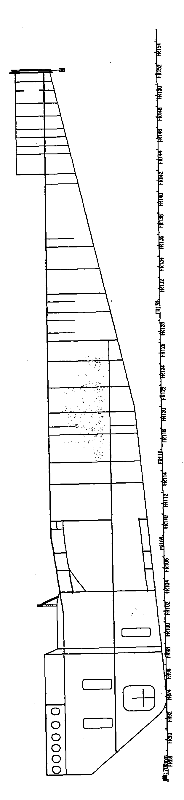
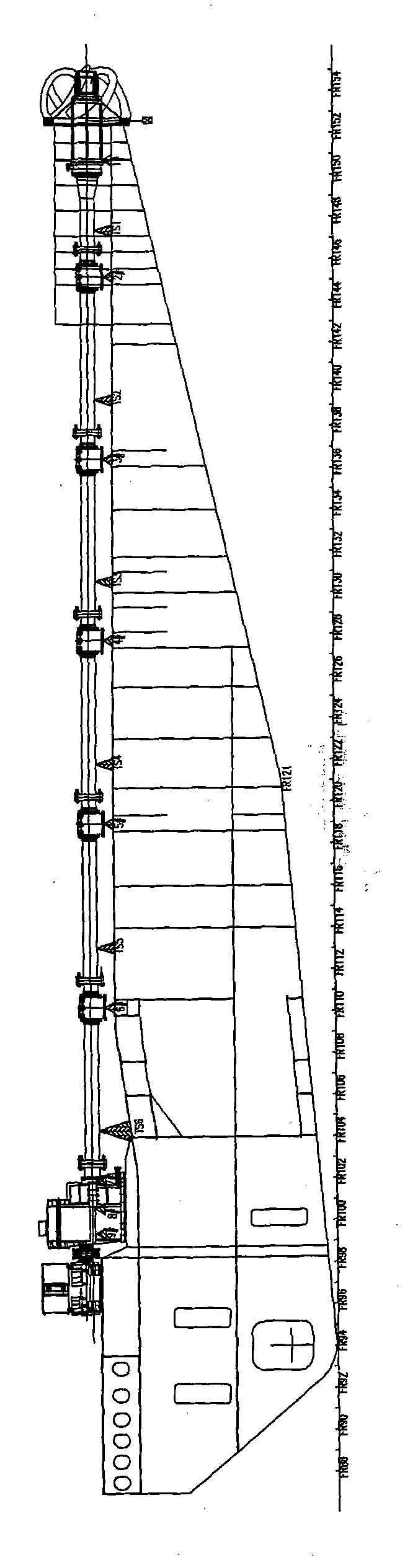
[0062] The ship's reamer is driven by two electric motors through a high-elastic friction clutch, a gear box, a long shaft supported by "Sailong" water-lubricated composite material bearings, and a reamer shaft supported by "Sailong" water-lubricated composite material bearings. The knife gearbox is mounted on top near the trunnion of the bridge.

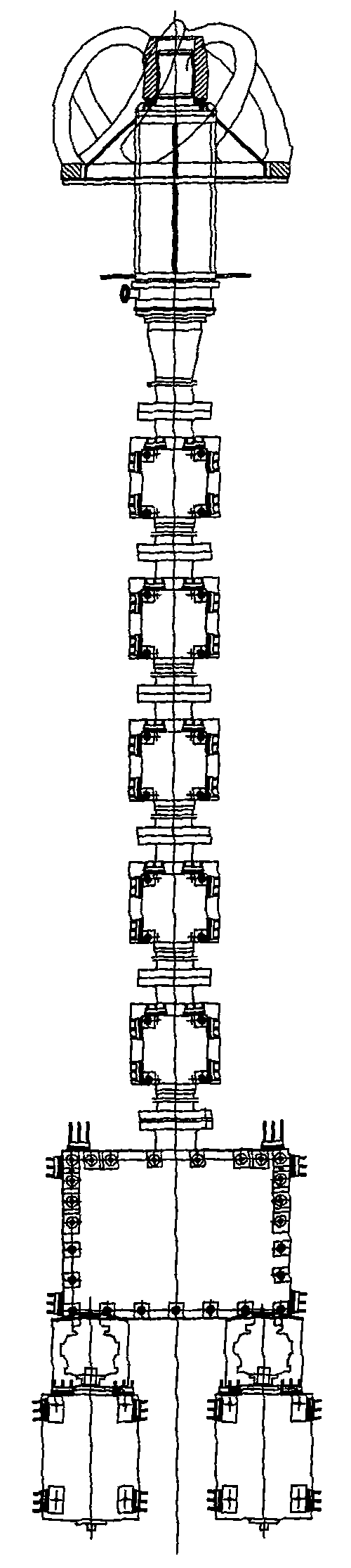
[0063] The reamer shaft system consists of 5 intermediate shafts, 5 intermediate bearings, a reamer bearing, water-sealed cooling and lubricating device, reaming pin sleeve, screw bearing pressure ring, combustion ring, seals, etc. Intermediate bearings and reamer bearings use "Sailong" water-lubricated composite material bearings.

[0064] The 2055mm bearing seat is assembled and welded after being pulled, calibrated, and bored underwater, and the "Sailong" water-lubricated composite bearing is installed. The motor, high elastic friction clutch, gear box, etc. are hoisted on the bridge frame on the berth for temporary support and ...


PUM


Abstract

The invention discloses a process for installing reamer transmission shafts of a cutter-suction dredge, comprising the steps of shaft alignment and installation, internal boring, infield machining, installation of a 'Cellon' water lubrication composite material bearing, rear shaft filling, installation of a sealing device, in-place installation of the front end shaft of the reamer shaft, fitted ground, shaft centering, accessory installation and the like. The invention has the advantages of convenient installation, good working effect and easy operation.

Description

Technical field: [0001] The invention relates to an installation process of a shaft system of a reamer drive shaft of a cutter suction dredger. Background technique: [0002] The installation process of the existing cutter suction dredger cutter transmission shaft shaft system is complex, the working effect is not ideal, and the technology is difficult. Invention content: [0003] The object of the present invention is to provide an installation process for the shaft system of the reamer drive shaft of a cutter suction dredger which is easy to install and has good working effect. [0004] Technical solution of the present invention is: [0005] A shafting installation process of the cutter transmission shaft of a cutter suction dredger is characterized in that it includes the following steps: [0006] (1) Shaft positioning and installation: [0007] Pull wire: [0008] The bow cable frame is located in the center of the large flange with a thickness of Φ2770×50 at the ...

Claims


Application Information

Patent Timeline
IPC IPC(8): E02F3/90
Inventor 孟锦华李江王国松
Owner 南通港闸船舶制造有限公司
Why Eureka
Try Eureka