External combustion tube type direct reduction shaft furnace

A combustion tube type and direct technology, applied in the field of direct reduction of shaft furnaces, can solve the problems of influence of reduction effect, unsmooth connection, long construction time, etc., and achieve the effect of good reduction effect, good heating effect and stable heating effect.

Inactive Publication Date: 2010-09-15
PANZHIHUA CHUANGSHENG POWDER METALLURGY
View PDF6 Cites 25 Cited by
  • Summary
  • Abstract
  • Description
  • Claims
  • Application Information

AI Technical Summary

Benefits of technology

This new design for reducing metal oxides by directly burning them into molten metals without generating harmful gases or polluting substances makes it possible to achieve higher efficiency than existing methods while minimizing environmental impacts associated therewith.

Problems solved by technology

This patented technical problem addressed in this patents relates to improving the design of an internal thermal reactor type directly fired shaft kiln process without requiring expensive facilities such as large steel cylindrical vessels.

Method used


Image

  • External combustion tube type direct reduction shaft furnace
  • External combustion tube type direct reduction shaft furnace
  • External combustion tube type direct reduction shaft furnace

Examples


Embodiment 1

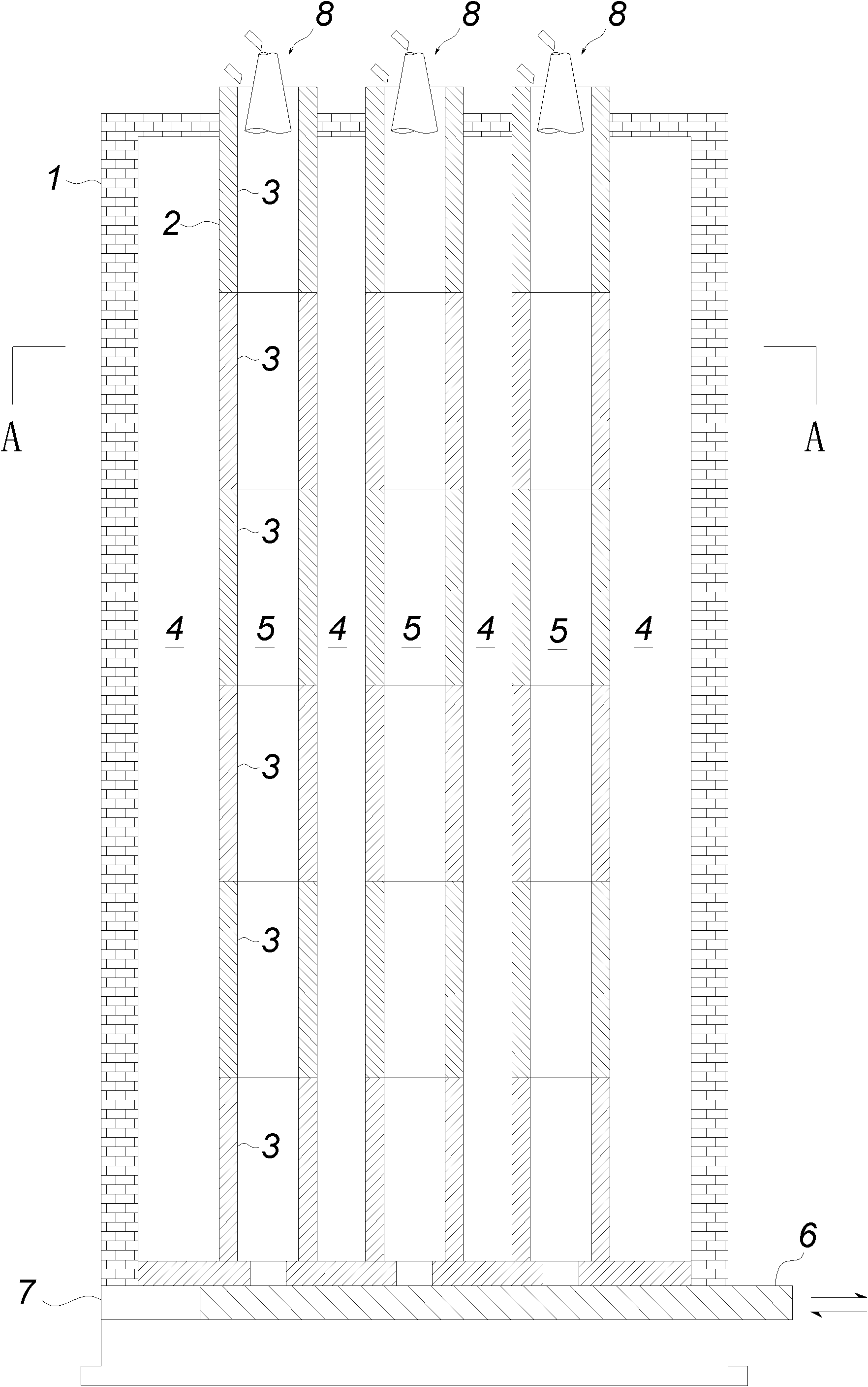
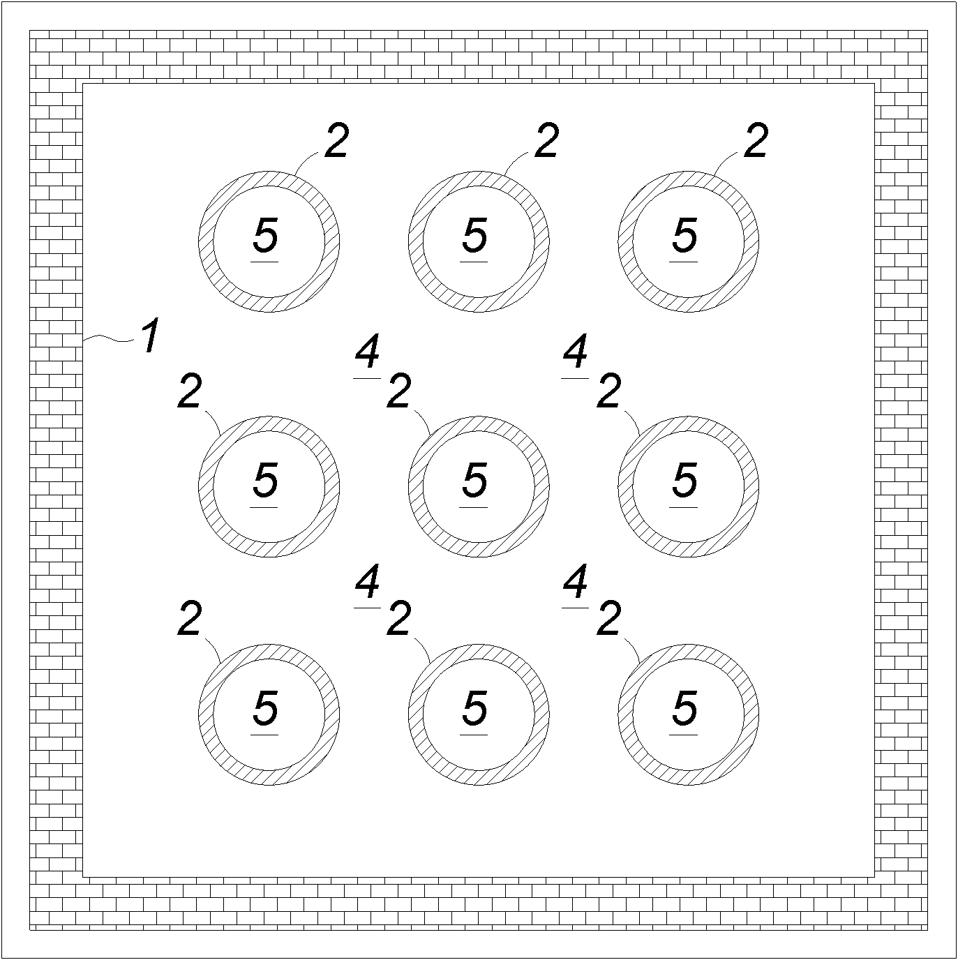
[0037] Such as Figure 1~3 In the shown external combustion tube type direct reduction shaft furnace, a plurality of reduction reaction tubes 2 are arranged in the furnace body 1, and the adjacent reduction reaction tubes 2 are arranged at intervals. The continuous area formed between the exterior of all the reduction reaction tubes 2 and the inner wall of the furnace body 1 is the combustion chamber 4 . Combustion chamber 4 adopts coal gas to ignite. Facilities such as the flue of combustion chamber 4 and the gas channel all can adopt existing structure, therefore do not show in the figure. With this arrangement, the surrounding area of ​​each reduction reaction tube 2 is a high-temperature environment for combustion, so that the materials in each reduction reaction tube 2 are heated more uniformly and stably. Root reduction reaction tube 2, thus ensuring the unit capacity of the shaft furnace.

[0038] Wherein, a distributing device 8 is provided at the upper port 201 of ...

Embodiment 2

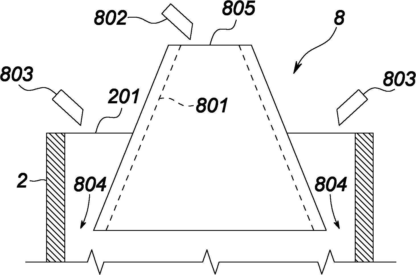
[0040] The difference between this embodiment 2 and embodiment 1 is that the structure of the distribution device 8 is different. Such as Figure 4 As shown, the distributing device 8 includes two inner and outer tubular members. Since the outer diameter of the inner tubular member is smaller than the inner diameter of the outer tubular member, an entry channel for the anti-sticking material is formed between the two tubular members. 804, and the lumen of the inner tubular member is the channel for the material undergoing the reduction reaction. Of course, the distributing device 8 still includes a discharger 802 and a discharger 803 for automatic supply of materials and release materials.


PUM


Abstract

The invention discloses an external combustion tube type direct reduction shaft furnace with better reduction effect. The external combustion tube type direct reduction shaft furnace comprises a furnace body which is provided with reduction chambers and a combustion chamber inside; at least one reduction reaction tube with two open ends is arranged inside the furnace body; the reduction chamber is formed inside the reduction reaction tube; and the combustion chambers are formed at the periphery. Because the combustion chambers are formed at the periphery of the reduction reaction tube in the external combustion tube type direct reduction shaft furnace, the shaft furnace has better heating effect on the reduction chamber and heats the materials more uniformly. The external combustion tube type direct reduction shaft furnace can also heat the materials more uniformly and stably on the basis of the separation of heating and reduction reaction. Therefore, the reduction effect is better.

Description


Claims


Application Information

Patent Timeline
Owner PANZHIHUA CHUANGSHENG POWDER METALLURGY
Why Eureka
Try Eureka