
Grate plate arrangement

A grid plate and grid technology, which is applied in the field of grid plate devices, can solve problems such as non-compliance with bolt pre-tightening force, and achieve the effect of preventing contact and preventing wear

Inactive Publication Date: 2010-09-15
IKN GMBH
View PDF9 Cites 2 Cited by
  • Summary
  • Abstract
  • Description
  • Claims
  • Application Information

AI Technical Summary

Problems solved by technology

However, it is necessary for this to turn the bolt to a certain position in which the sides rest against the wrench faces, which generally does not correspond to the optimum bolt pretension

Method used


Image

  • Grate plate arrangement
  • Grate plate arrangement
  • Grate plate arrangement

Examples


Embodiment Construction

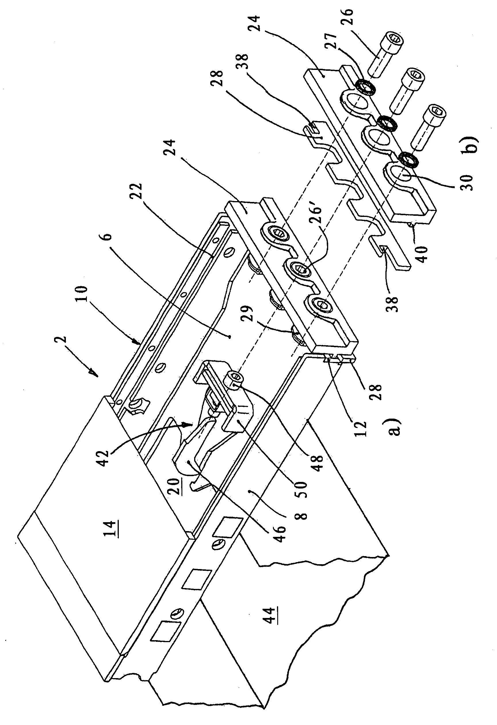
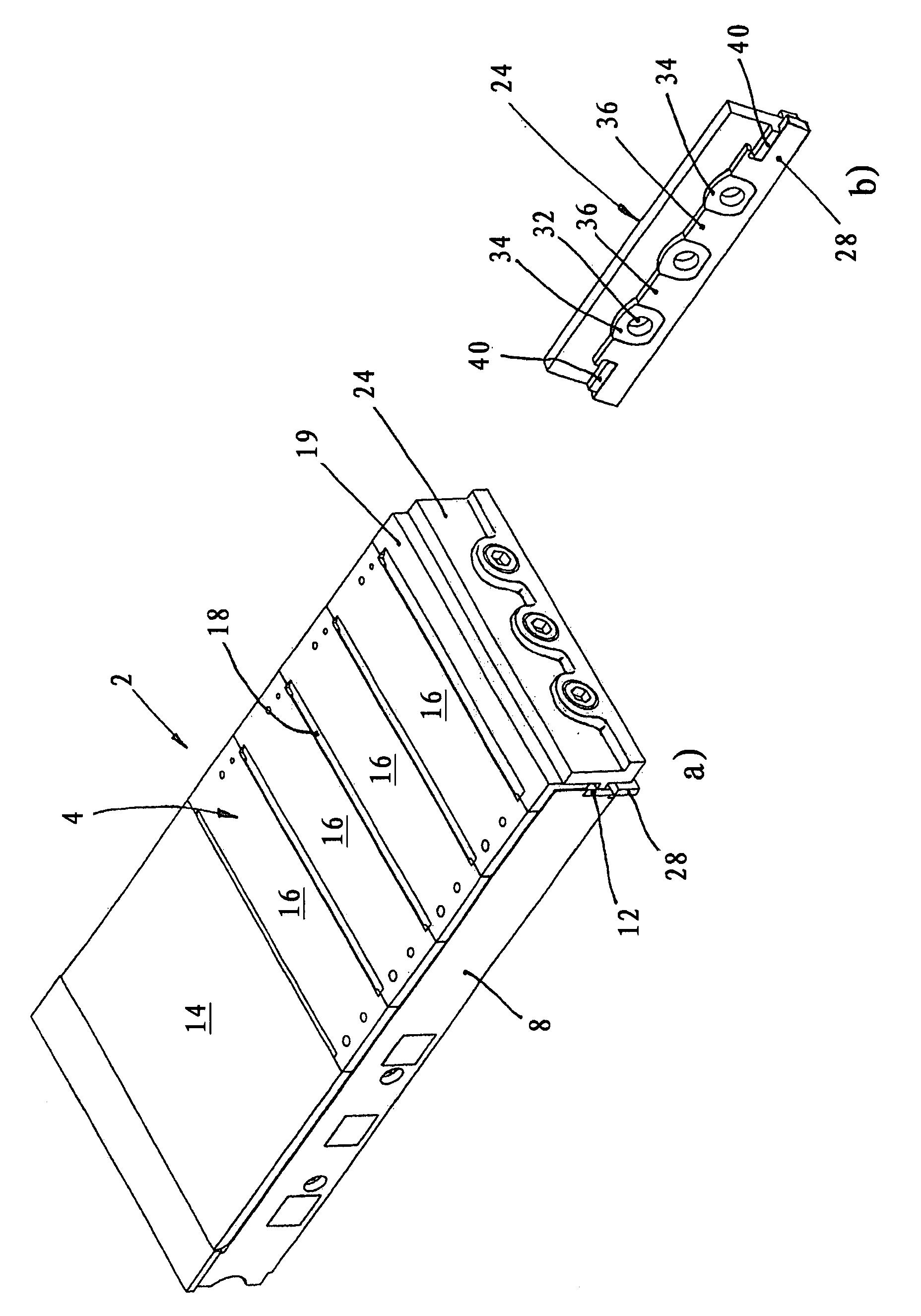
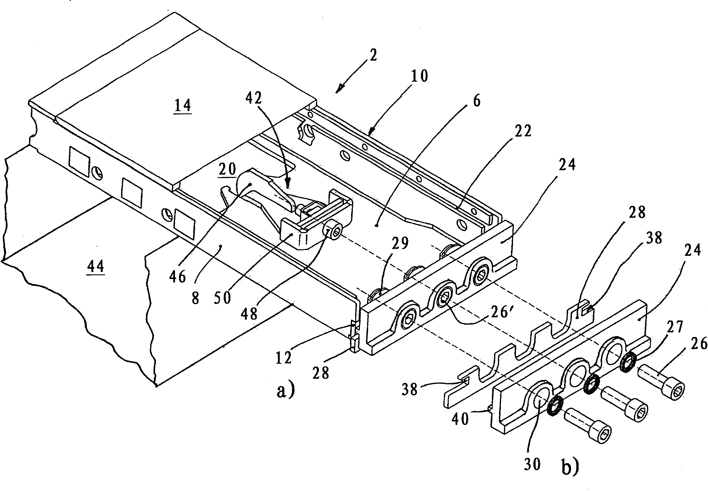
[0027] exist figure 1 The grid panels 2 shown in a and 2a have a substantially conventional construction. It is approximately box-shaped and comprises a cover wall 4 , a bottom wall 6 , two side walls 8 , 10 , a rear wall not visible in the drawing, and a front wall 12 .

[0028] as special figure 2 It can be seen that the cover wall 4 basically comprises: a closed starting sheet 14, which roughly corresponds to an overlapping region with a front not shown grid sheet; a plurality of intermediate sheets 16, between which respectively There remains a blowing slit; and a curved end sheet 19 which constitutes the closure of the cover wall 4 with the upper region of the front wall 12 .

[0029] In its rear region, the bottom wall 6 has an opening 20 , through which it rests on a grill support 44 , through which opening, for example, cooling air is introduced into the grill plate.

[0030] The cooling air flows through the blowing slits 18 into the bulk material lying on the gri...


PUM


Abstract

A grate plate arrangement for stepped reciprocating grates includes a box-like grate plate (2) with a front plate (24) fastened to a front wall (12) in the direction of conveyance; means for adjusting a motion gap between the front end of the grate plate and the following grate plate in the direction of conveyance which forms the next grate step includes a separate adjustment plate (28), which is non-positively clamped between the front plate (24) and the front wall (12) of the grate plate. The adjustment plate (28) is calibrated with the front plate (24) still only loosely assembled, in its vertical position that forms the motion gap, and is held in this position by clamping the front plate. A clamping bolt (48) for clamping the grate plate (2) on a grate carrier (44) can be arranged such that the clamping bolt (26') aligns with a fixing bolt for the front plate (24) so that the clamping bolt can be actuated though access openings for this fixing bolt.

Description

technical field [0001] The invention relates to a grid panel arrangement for a graded sliding grid according to the preamble of claim 1 . Background technique [0002] A graded sliding grate is used for continuous conveying and simultaneous cooling or other treatment of loose material which is accumulated on the grate and fed from below through the grate surface provided with a plurality of air holes Cooling air or another process gas. [0003] A plurality of grid plates arranged side by side on a grid support form a grid row, and a plurality of grid rows arranged successively along the conveying direction form a grid. In the case of sliding grids, the individual grid rows are movable back and forth in the conveying direction, whereby the loose material placed on the grid is conveyed forward via the grid. [0004] The "box-like" grid panels form a substantially closed flat box comprising a cover wall, a bottom wall, two side walls and a front wall and a rear wall. Via a h...

Claims


Application Information

Patent Timeline
Patent Type & Authority Applications(China)
IPC IPC(8): F27D15/02F27B21/08
CPCF27D15/022
Inventor N·范迪彭R·施奈德S·K·温德默勒
Owner IKN GMBH
Learn More