Dehumidifier with function of movable air conditioner

A technology for mobile air conditioners, dehumidifiers, applied in air conditioning systems, space heating and ventilation, space heating and ventilation details, etc.

Inactive Publication Date: 2010-09-22
LG ELECTRONICS (TIANJIN) APPLIANCES CO LTD
View PDF0 Cites 11 Cited by
  • Summary
  • Abstract
  • Description
  • Claims
  • Application Information

AI Technical Summary

Problems solved by technology

[0006] However, dehumidifiers with traditional structures can only achieve the function of air dehumidification; mobile air conditioners can only achieve the function of temperature adjustment

Method used


Image

  • Dehumidifier with function of movable air conditioner
  • Dehumidifier with function of movable air conditioner
  • Dehumidifier with function of movable air conditioner

Examples


Embodiment Construction

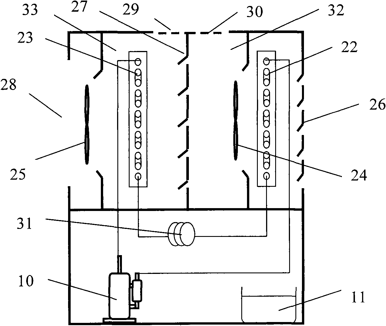
[0014] Below in conjunction with accompanying drawing and specific embodiment the present invention is described in further detail:

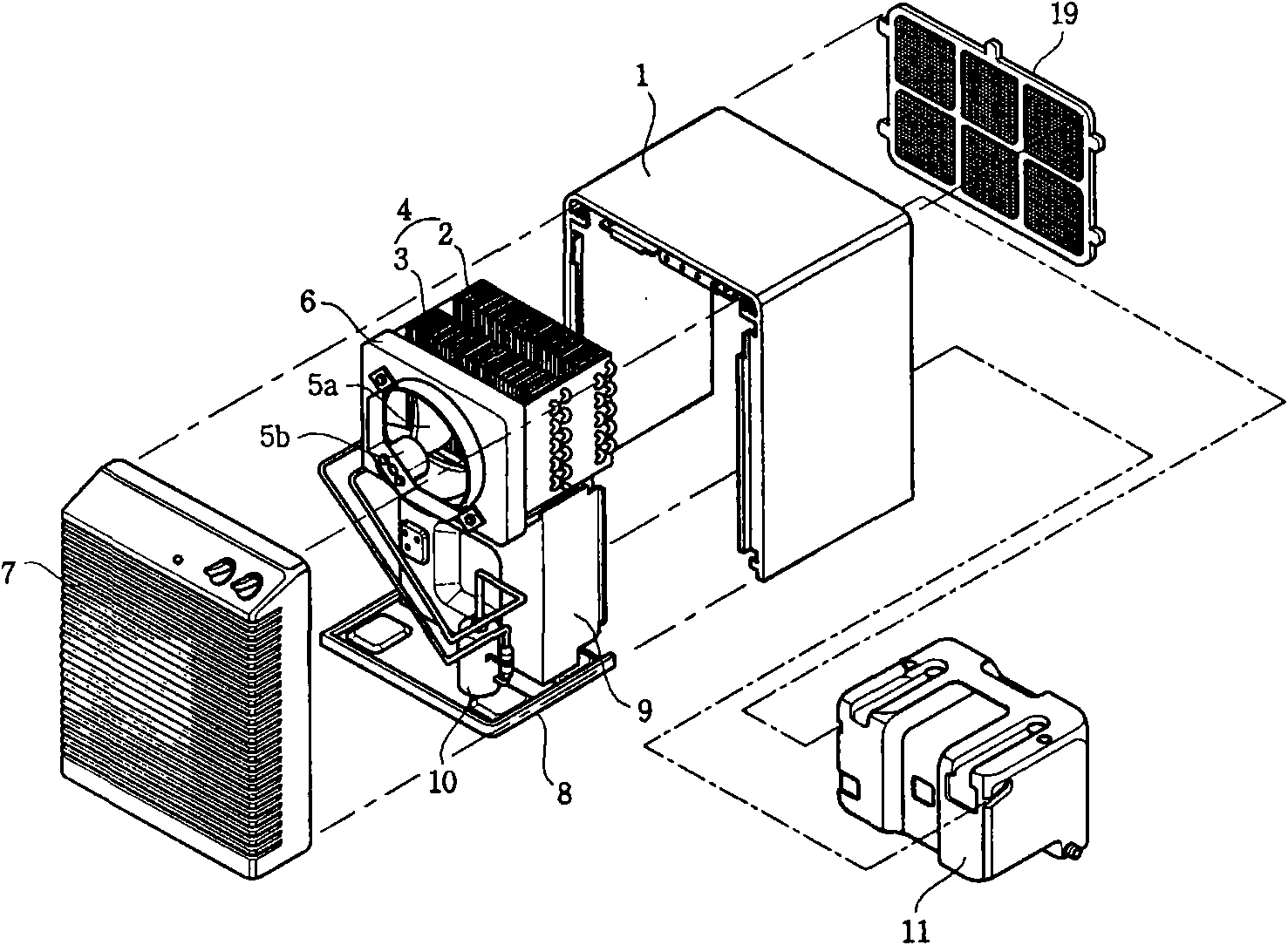
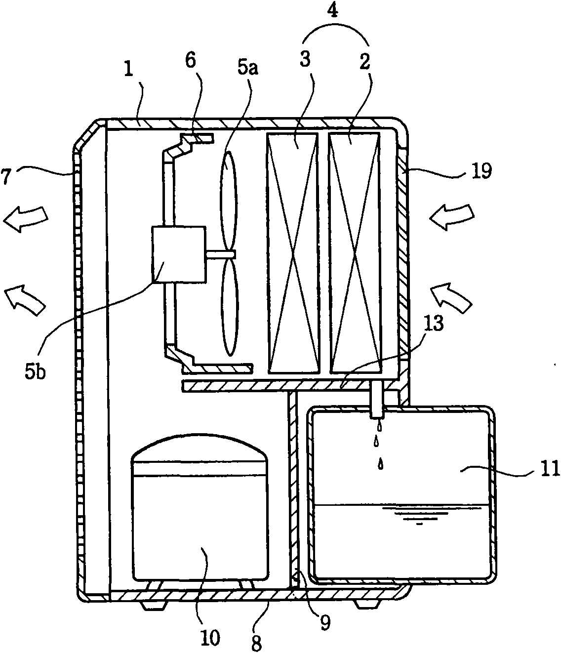
[0015] Such as image 3 , 4 As shown, the dehumidifier with mobile air conditioning function of the present invention includes a casing formed with an air inlet and an air outlet; a heat exchanger composed of an evaporator 22 and a condenser 23, and a bucket 11 for storing condensed water , the blower fan and motor that suck the air in the room into the inside of the cabinet and then discharge it, and the compressor 10 that compresses the refrigerant circulating in the evaporator 22 and the condenser 23, and the evaporator 22 and the condenser 23 are connected with Throttle valve 31, evaporator 22 is located on the inner side of the rear shell with the first air inlet 26 on the upper part of the dehumidifier, and the condenser 23 is located on the inner side of the front shell with the first air outlet 28 on the upper part of the dehumidifier. ...


PUM


Abstract

The invention discloses a dehumidifier with a function of a movable air conditioner, which comprises machine shell, a heat exchanger, a water receiving bucket, a blower, a motor and a compressor, wherein a first controllable baffle plate dividing an upper space into an independent evaporator space and an independent condenser space is arranged between an evaporator and a condenser; a second controllable baffler plate is arranged on the machine shell above the evaporator space close to the first controllable baffle plate; a third controllable baffle plate is arranged on the machine shell above the condenser space close to the first controllable baffle plate; guide blades are arranged on the second and third controllable baffle plates; and the evaporator space and the condenser space are communicated with and separated from the outside by the opening and closing of the guide blades. The functions of the dehumidifier can be realized independently in a set of refrigeration equipment, and can also be used alone as a mobile air conditioner. Through the simple change of the baffle plates, a flow channel can be changed to realize different functions.

Description

technical field [0001] The invention relates to a dehumidifier, in particular to a dehumidifier with the function of a mobile air conditioner. Background technique [0002] Such as figure 1 and figure 2 As shown, the dehumidifier in the prior art includes: a casing 1 that constitutes the appearance of the left and right sides and the top, and the front, rear and bottom surfaces are open; the evaporator 2 and the condenser 3 that are arranged inside the casing 1 The heat exchanger 4 for dehumidification; the compressor 10 for compressing the refrigerant circulating in the evaporator 2 and the condenser 3; it is arranged in front or behind the heat exchanger 4 and generates wind power to suck the indoor air into the casing 1 and then discharged to the indoor blower fan 5a and motor 5b; arranged in front of the casing 1, so that the dehumidified air flowing through the heat exchanger 4 is discharged to the outside of the front panel 7 formed with a grid; arranged in The bot...

Claims


Application Information

Patent Timeline
Patent Type & Authority Applications(China)
IPC IPC(8): F24F1/02F24F13/30
Inventor 张金兰杨佩元
Owner LG ELECTRONICS (TIANJIN) APPLIANCES CO LTD
Why Eureka
Try Eureka