Staggered system of air conditioner of subway vehicle with UVC sterilization

A technology for vehicle air conditioning and heat exchange system, which is applied to the pipeline arrangement of subway vehicle air conditioning unit system and the field of disinfection and purification of air inside the unit. Thermal effect, health maintenance effect

Active Publication Date: 2012-09-26
ZHEJIANG DUNAN ARTIFICIAL ENVIRONMENT
View PDF0 Cites 2 Cited by
  • Summary
  • Abstract
  • Description
  • Claims
  • Application Information

AI Technical Summary

Problems solved by technology

[0005] At present, the air-conditioning units of subway vehicles are used to adjust the temperature and humidity of the air, without disinfection and purification treatment.

Method used


Image

  • Staggered system of air conditioner of subway vehicle with UVC sterilization
  • Staggered system of air conditioner of subway vehicle with UVC sterilization
  • Staggered system of air conditioner of subway vehicle with UVC sterilization

Examples


Embodiment 1

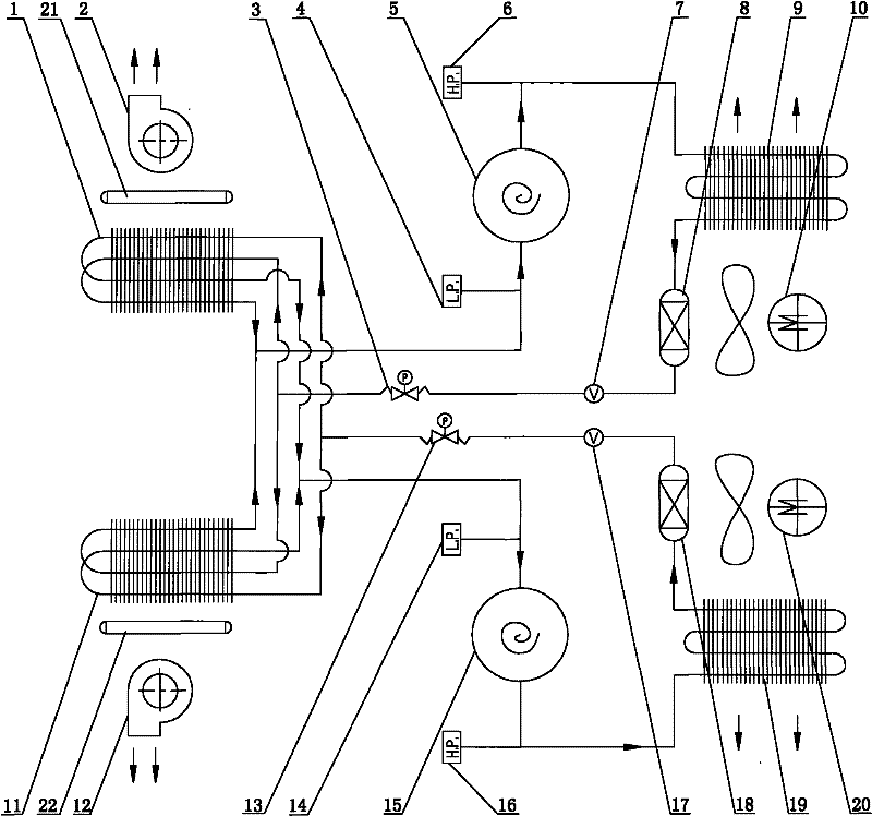
[0021] Such as figure 1 As shown, the number of the heat exchange systems is two, and the two heat exchange systems are interlaced, that is, the output end of the first throttling device 3 is connected to the input end of the first evaporator 1 and the input end of the second evaporator 11 respectively. The input end, the output end of the first evaporator 1 and the output end of the second evaporator 11 are all connected to the input end of the first compressor 5, and the first UVC sterilization device 21 is installed on the air outlet side of the first evaporator 1; The output end of the second throttling device 13 is respectively connected to the input end of the first evaporator 1 and the input end of the second evaporator 11, and the output end of the first evaporator 1 and the output end of the second evaporator 11 are connected to At the input end of the second compressor 15 , the second UVC sterilization device 22 is installed on the air outlet side of the second evapo...

Embodiment 2

[0030] The number of the heat exchange systems is 4, and the 4 heat exchange systems are interlaced in pairs, that is, the output end of the first throttling device is respectively connected to the input end of the first evaporator and the input end of the second evaporator. Both the output end of the first evaporator and the output end of the second evaporator are connected to the input end of the first compressor, and the first UVC sterilization device is installed on the air outlet side of the first evaporator; the output ends of the second throttling device are respectively Connected to the input end of the first evaporator and the input end of the second evaporator, the output end of the first evaporator and the output end of the second evaporator are both connected to the input end of the second compressor, and the second UVC sterilization device Installed on the air outlet side of the second evaporator; the output end of the third throttling device is respectively connec...


PUM


Abstract

The invention discloses a staggered system of an air conditioner of a subway vehicle with UVC sterilization, which comprises at least two heat exchange systems which are mutually staggered. The heat exchange systems comprise condensers, dry filters, throttling devices, evaporators, compressors, axial flow fans and ventilators, which are sequentially connected end to end and form a closed loop. The air inlet sides or the air outlet sides of the evaporators are provided with UVC sterilization devices. By adopting the mutually staggered structure of the systems, the problem of overlarge temperature difference of an outlet of each ventilator when a machine set runs in a half cold (half warm) mode is solved; and the UVC sterilization devices are installed at the air inlet sides or the air outlet sides of the evaporators, which kills microorganisms, such as bacteria and the like, on the evaporators and in ventilation air effectively, decreases the air resistance and ensures the heat exchange effect. The UVC sterilization devices do not generate a pollution source and is unlike to other detergents which cause the condition that passengers contact with dangerous chemical substances or toxic smog to cause the injury of a human body. The invention can be suitable for the air conditioning units of various subway vehicles and has very extensive market prospect.

Description

【Technical field】 [0001] The invention relates to the field of subway vehicle air-conditioning products, in particular to the pipeline arrangement of the subway vehicle air-conditioning unit system and the air disinfection and purification inside the unit. 【Background technique】 [0002] At present, most subway car air conditioning units use two independent systems. One compressor independently controls one system, and the evaporator and condenser in the system are connected separately. The two systems are not related to each other. [0003] When the air conditioning unit is running in "semi-cool" or "semi-warm" mode, one system works and the other system stops. This causes one system to cool or heat and the other to ventilate. The outlet air temperature of the two ventilators is inconsistent. [0004] During the use of subway vehicle air conditioners, the maintenance interval is long, and the interior of the air conditioner unit has not been cleaned for a long time, and d...

Claims


Application Information

Patent Timeline
Patent Type & Authority Patents(China)
IPC IPC(8): F25B5/02F25B41/06A61L2/10A61L9/20
CPCY02B30/72Y02B30/70
Inventor 潘昌林李学燎吴松辉张博学钟建法
Owner ZHEJIANG DUNAN ARTIFICIAL ENVIRONMENT
Why Eureka
Try Eureka