Measurement stand and method of its electrical control

A technology of electrical control and measuring bench, applied in the field of measuring bench

Inactive Publication Date: 2010-09-22
HELMUT FISCHER & INSTITUT FUR ELECTRONIK & MESSTECHN
View PDF13 Cites 20 Cited by
  • Summary
  • Abstract
  • Description
  • Claims
  • Application Information

AI Technical Summary

Problems solved by technology

In order to meet the growing need for flexibility in performing measurements and reducing the number of disassembly and a

Method used


Image

  • Measurement stand and method of its electrical control
  • Measurement stand and method of its electrical control
  • Measurement stand and method of its electrical control

Examples


Embodiment Construction

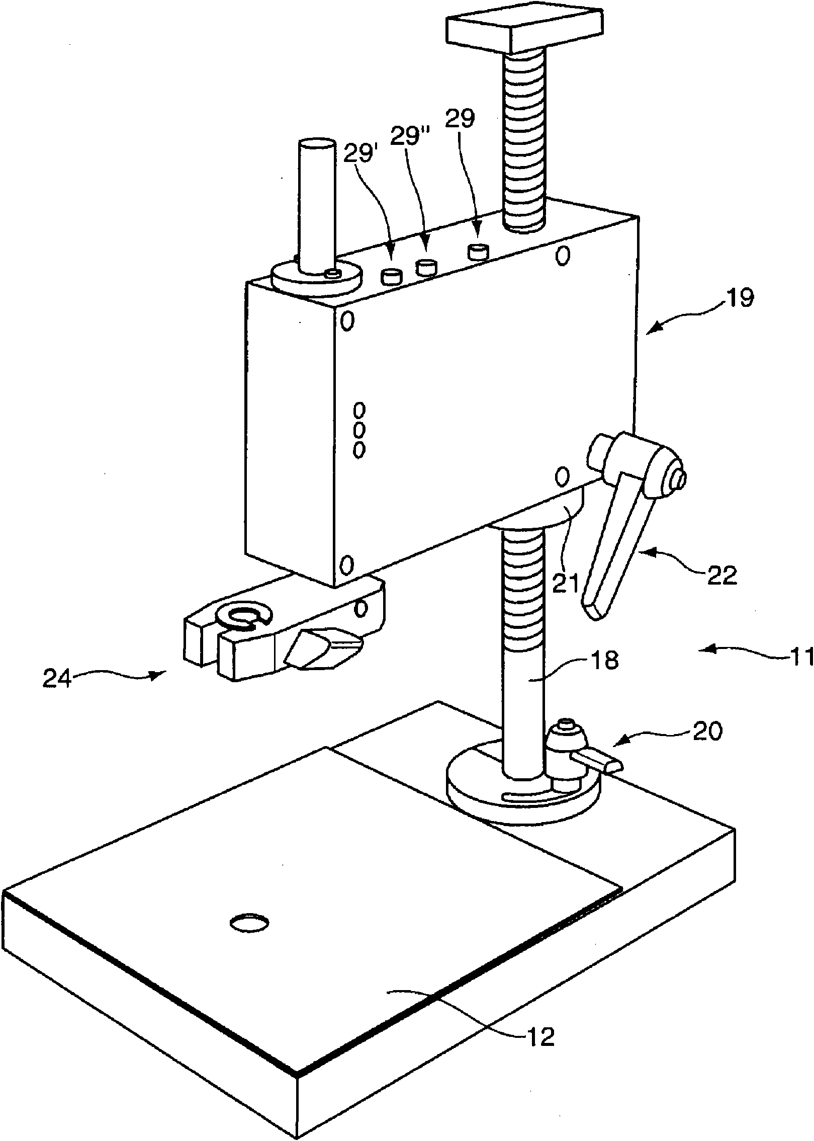
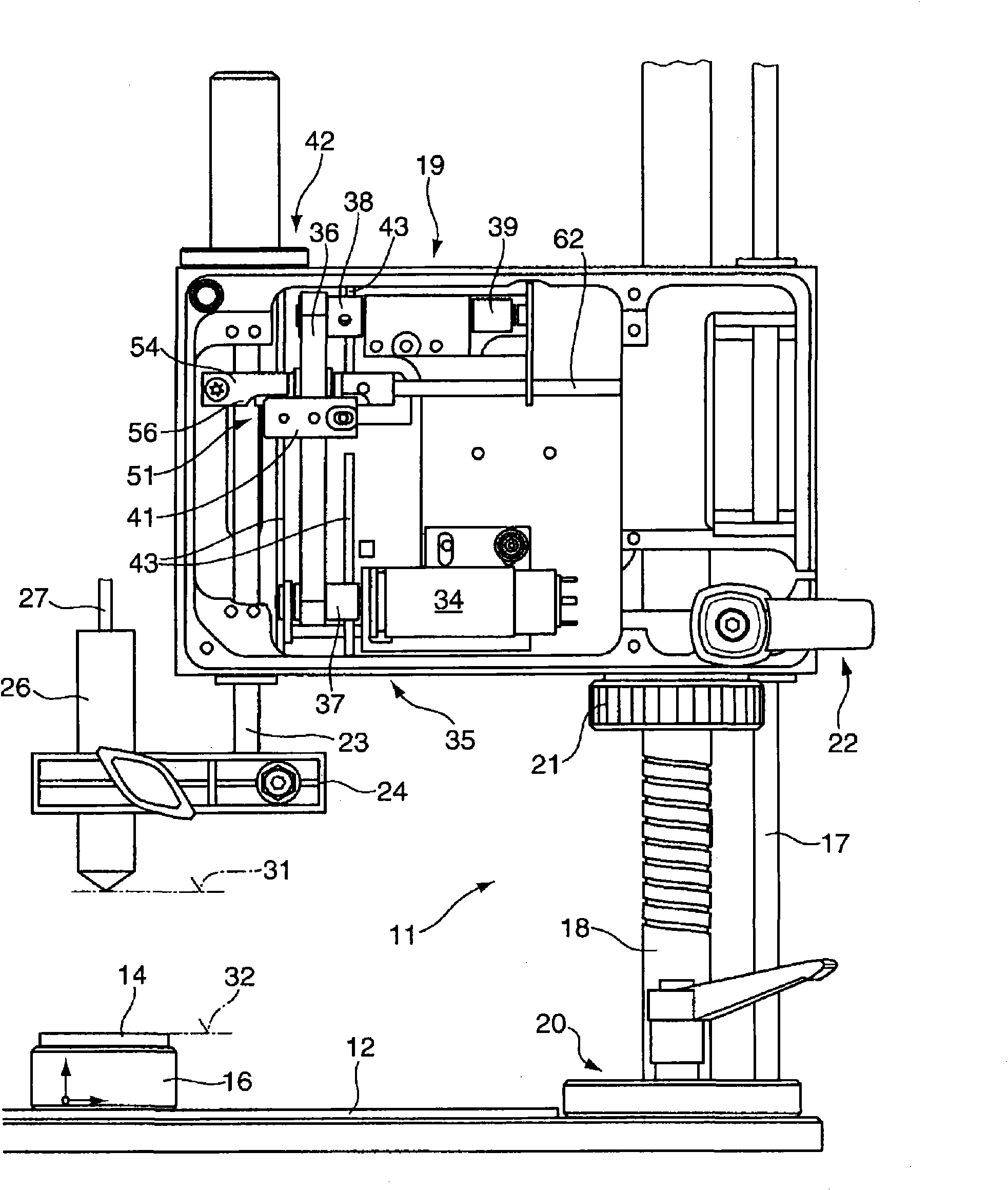
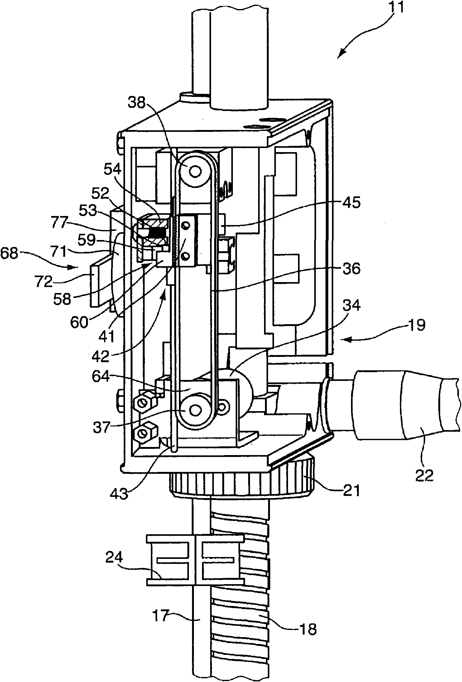
[0045] figure 1 The measuring bench 11 according to the invention is shown in perspective, figure 2for side view. The measuring bench 11 comprises a measuring table 12 on which individual test or measuring objects 14 can be placed directly or held by holders 16 . On the base of the measuring bench 11 or on the measuring table 12, a column 17 is arranged, and a housing 19 is installed on the column 17 and the threaded column 18 in a height-adjustable manner. By virtue of the two columns 17 , 18 being arranged next to each other, a parallel guidance that is easy to adjust in height can be achieved. The orientation of the housing 19 is effected by an adjustment mechanism 20 . The height can be set via set screw 21 . In addition, a clamping mechanism 22 is provided in order to fix the housing 19 at a certain height relative to the measuring table 12 .

[0046] On the side opposite to the columns 17 , 18 , a displacement member 23 is mounted on the housing 19 in a movable man...


PUM


Abstract

The invention relates to a measurement stand for holding a measuring probe intended in particular for measuring the thickness of thin layers, and to a method for controlling the measurement stand.

Description

technical field [0001] The invention relates to a method of electrically controlling a measuring gantry to provide a movement of at least one measuring probe traveling from a starting position to a measuring position, in particular for measuring the thickness of thin layers, and to a method for performing the Measuring bench for the method described above. Background technique [0002] DE 10 2005 034 515 A1 discloses a measuring stand for holding measuring probes designed for measuring the thickness of thin layers. The measuring bench comprises a housing in which the displacement member can be guided so that it moves up and down. At its end facing the object to be measured, a holder for fixing the measuring probe is provided. The up and down movement of the displacement member is initiated by a motor-controlled drive unit. The upper end position and the lower end position of the up and down movement of the displacement member are respectively detected by the detectors. T...

Claims


Application Information

Patent Timeline
IPC IPC(8): G01B5/00G01B5/06G01B7/06
CPCG01B7/105G01B5/0004G01B5/066G01B21/08G05B19/425G01B5/06G01B7/06
Inventor H·费希尔
Owner HELMUT FISCHER & INSTITUT FUR ELECTRONIK & MESSTECHN
Why Eureka
Try Eureka