
A sliding rod type travel changeover switch

A transfer switch, sliding rod technology, applied in electrical switches, electrical components, circuits, etc., can solve the problems of single function and poor adaptability of travel switches, and achieve the effect of simple implementation, simple manufacturing and broad market space

Inactive Publication Date: 2011-12-14
STATE GRID CORP OF CHINA +2
View PDF2 Cites 0 Cited by
  • Summary
  • Abstract
  • Description
  • Claims
  • Application Information

AI Technical Summary

Problems solved by technology

[0008] The purpose of the present invention is to overcome the shortcomings of the current known travel switch such as single function and poor adaptability, and provide the public with a unique travel position control device

Method used

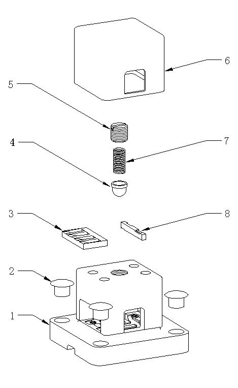
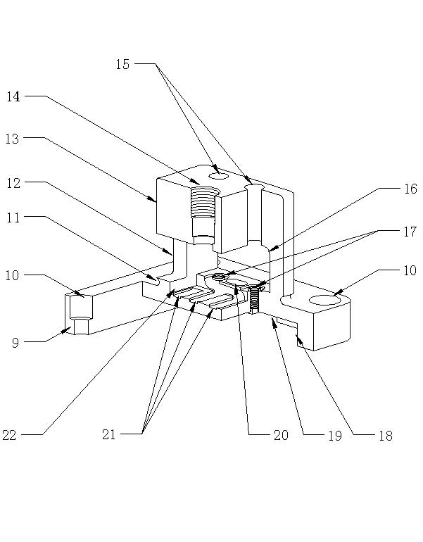

Image

  • A sliding rod type travel changeover switch
  • A sliding rod type travel changeover switch
  • A sliding rod type travel changeover switch

Examples


Embodiment Construction

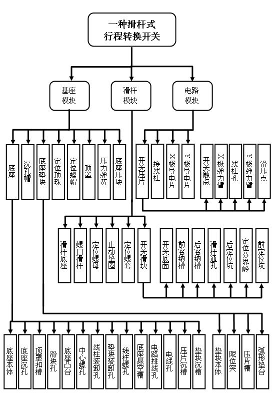
[0035] As a technical solution for product manufacturing, the present invention can be implemented through the organic combination of corresponding modules and parts. The product organizational structure of an embodiment of the present invention is as figure 1 shown.

[0036] figure 1 Among them, the product of the present invention is composed of three modules: a base module, a slide bar module, and a circuit module; each different module is composed of corresponding different parts; wherein, the base module is composed of a base, a counterbore cap, a base pad Block, positioning top bead, positioning nut, top cover, pressure spring, and base pressing block are composed of eight parts; the slider module is composed of a slider base, a screw slide rod, a positioning nut, a stop washer, a positioning screw sleeve, and a switch slider Composed of six parts; the circuit module is composed of four parts: switch pressing plate, terminal post, X pole guide piece, and Y pole guide p...


PUM


Abstract

The invention relates to a switching device for a current direction, especially to a stroke switch that employs a structure with a slide bar type and enables the current direction to be converted bidirectionally. According to a widely-known stroke switch at present, there are defects including signal function and weak adaptability and the like; however, an objective of the invention is to overcome the above-mentioned defects so as to provide a unique control device for a stroke position. The stroke conversion switch is composed of eighteen parts including a pedestal, hole sinking caps, a pedestal cushion block, a positioning top button, a positioning nut, and a top boot and the like and three modules that include a pedestal module, a slide bar module, and a circuit module are formed. According to the invention, the stroke conversion switch enables a mechanical shift of a moving object to be converted into an electrical signal, wherein the widely-known stroke switch also has such a conversion function; in addition to the above-mentioned conversion, the stroke conversion switch also has advantages of bidirectional on-off power supply, current direction switching, accurate stroke distance arrangement, and automatic procedure arrangement and the like. In addition, the switch has characteristics of simple implementation and simple manufacture; and a product that is manufactured is solid and durable as well as can be used conveniently; therefore, the stroke conversion switch has broad market space and high economic value added.

Description

technical field [0001] The invention relates to a current direction switching device, in particular to a travel switch which adopts a slide bar structure and bidirectionally switches the current direction. [0002] Background technique [0003] Travel switch is a kind of position switch (also known as limit switch), and it is a commonly used small current master electrical appliance. It uses the collision or approach of the moving object to make the contact of the travel switch act, so as to achieve the purpose of connecting or breaking the circuit and controlling the movement of the electric object. Usually, the limit switch is used to limit the movement position or movement stroke of the electric object, so that the moving object will automatically stop, reverse movement, variable speed movement or automatic reciprocating displacement according to a certain position or stroke. [0004] The main function of the limit switch is to convert the mechanical displacement of the...

Claims


Application Information

Patent Timeline
Patent Type & Authority Applications(China)
IPC IPC(8): H01H3/16H01H3/32H01H9/54
Inventor 钟婕
Owner STATE GRID CORP OF CHINA
Learn More