Plate member and support member connection

a technology of support member and plate, applied in the field of connection, can solve the problems of cyclical load of support beams, unpredictable flexural behaviour and mechanical play in the connection of support beams and vertical support posts, and achieve the effect of significantly reducing the deflection and stress of lateral support beams

Inactive Publication Date: 2010-10-07
MULHOLLAND ANTHONY G
View PDF26 Cites 7 Cited by
  • Summary
  • Abstract
  • Description
  • Claims
  • Application Information

AI Technical Summary

Benefits of technology

[0007]The applicant has appreciated that the deflection and stress in the lateral sup

Problems solved by technology

This results in cyclical loading of the support beams.
This results in an amount of mechanical play in the connection of the support beams and the vertical support posts.
A problem exists in that small amounts of mechanical play allow rotation between the support beams and the vertical posts which makes the flexural behaviour of the lateral support beams somewhat unpredictable.
This results in an undesirable condition t

Method used


Image

  • Plate member and support member connection
  • Plate member and support member connection
  • Plate member and support member connection

Examples


Embodiment Construction

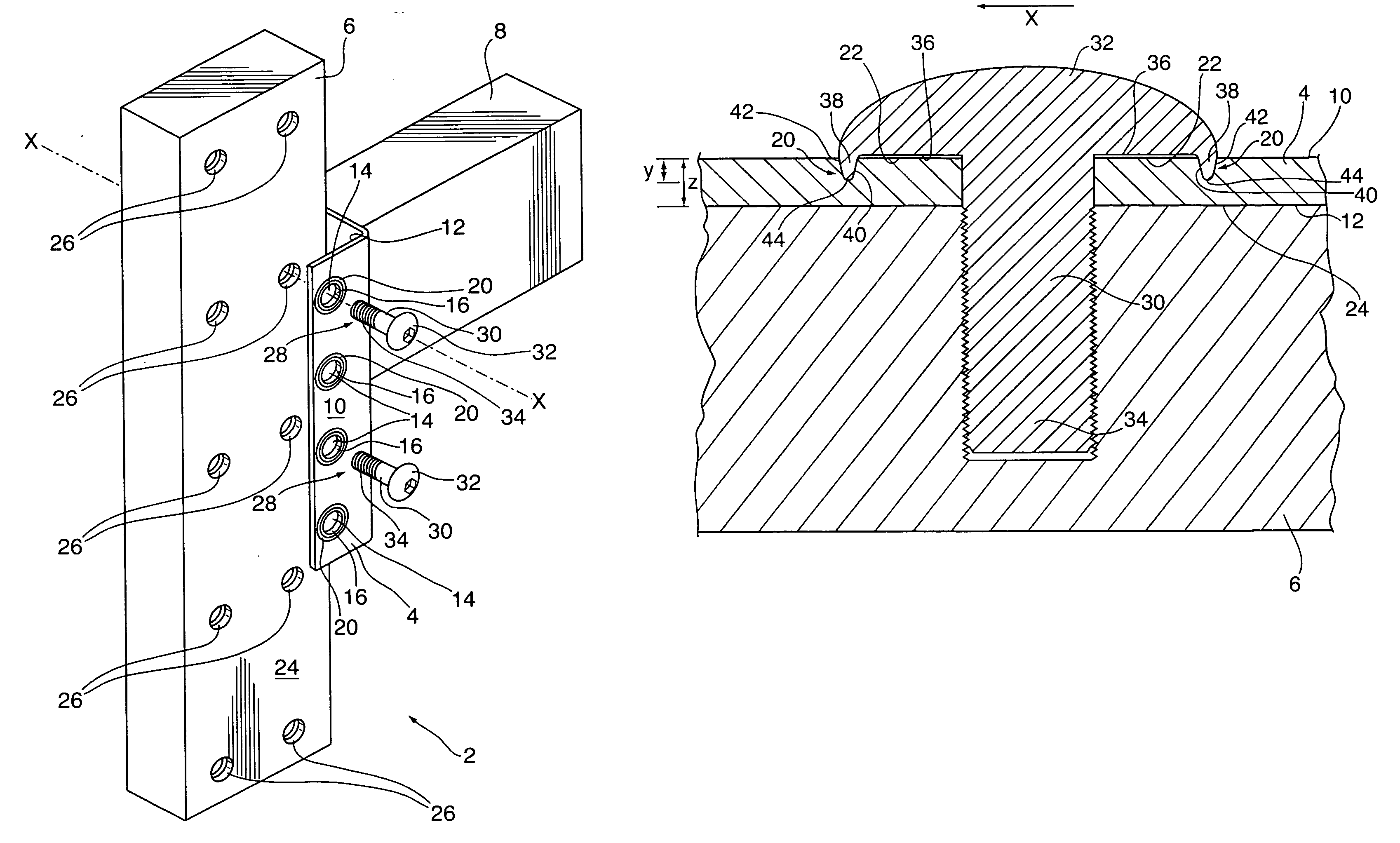
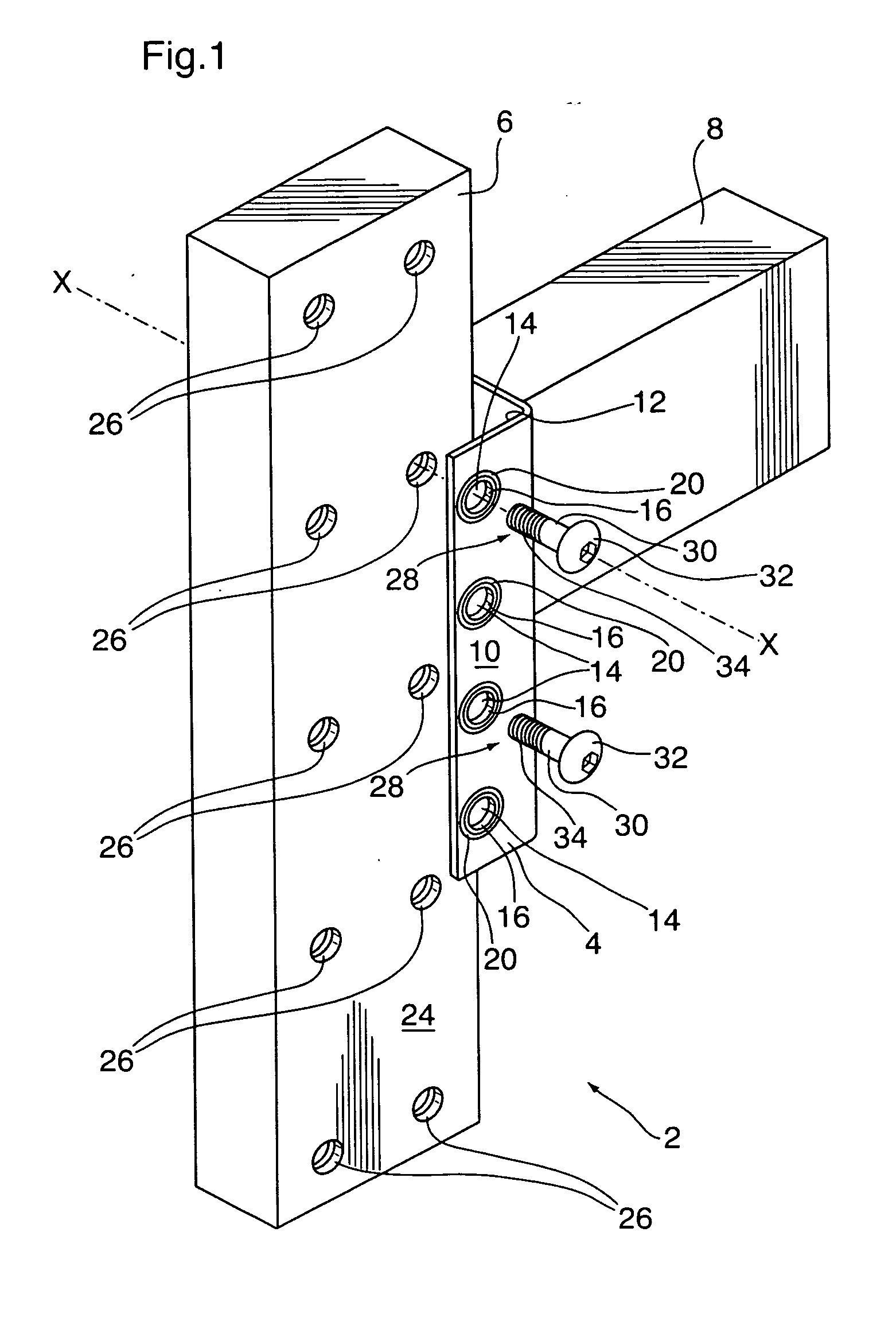
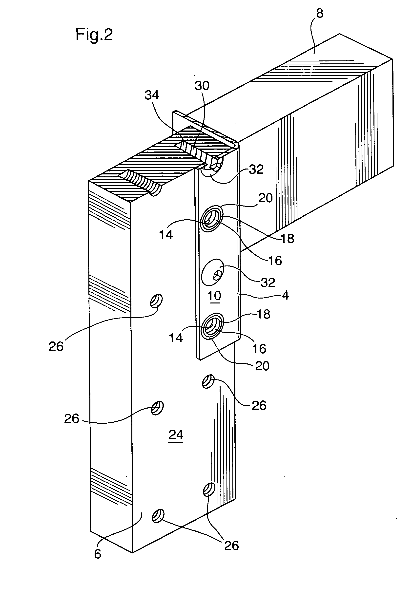
[0027]FIG. 1 shows, in exploded view, a connection 2 between a planar plate member 4 and a vertical support member 6. As shown, the planar plate member 4 is an angle bracket fixed to a horizontal beam 8.

[0028]The planar plate member 4 has a front surface 10 and a rear surface 12. Circular holes 14 extend through the plate member 4 from the front surface 10 to the rear surface 12. As shown, the holes 14 are disposed about an axis X-X normal to the front surface 10.

[0029]The circular holes 14 are defined within a circumferential wall 16 extending between the front surface 10 and the rear surface 12. A circumferential juncture 18 is defined at a merging of the circumferential wall 16 and the front surface 10.

[0030]An annular groove 20 extends into the front surface 10 of the plate member 2 towards the rear surface 12. The annular groove 20 is positioned radially outwardly from the circumferential wall 16 to define an annular land 22 between the circumferential juncture 18 and the annul...


PUM


Abstract

A connection between a plate and a support member. The plate has a front surface and a rear surface with a hole therethrough. An annular groove extends into the front surface positioned radially outwardly from the hole defining an annular land between the hole and the groove. The support member has a front surface and a back surface with a hole therethrough. A bolt has a shaft between a head and a threaded portion. The head has an underside with an annular boss. The shaft is positioned through the plate hole with the head engaging the plate front surface, and the annular boss positioned in the annular recess. The threaded portion extends through the support member and a threaded nut is fixed thereon. The nut has an engaging face with protrusions. When the nut is tightened, the protrusions bite into the support member back surface.

Description

FIELD OF THE INVENTION[0001]This invention relates to a connection for connecting two members together, in particular a planar plate member to a support member. More particularly, the connection is for connecting pallet rack upright frame members to lateral support members having brackets.BACKGROUND OF THE INVENTION[0002]Storage racks for supporting pallets or the like are well known in the art. Conventional storage racks typically include an upright frame structure. The frame structure has vertical support posts spaced horizontally with lateral support beams having first and second ends fixed to the support posts at selected vertical elevations. The lateral support beams support pallets. Typically, lift trucks or other suitable devices are used to place and remove pallets on the support beams. In many applications, the storage racks are used to store inventory, and thus pallets are repeatedly added and removed from the support beams as inventory fluctuates. This results in cyclical...

Claims


Application Information

Patent Timeline
IPC IPC(8): F16B5/02
CPCF16B5/025Y10T403/4668F16B37/04F16B35/06F16B2200/205
Inventor MULHOLLAND, ANTHONY G.
Owner MULHOLLAND ANTHONY G
Why Eureka
Try Eureka