Undersampling mixer circuit

A mixing circuit and under-sampling technology, applied in the field of signal mixing, can solve the problems of low sampling frequency and inability to meet high-frequency test circuits, and achieve the effect of ensuring accuracy

Active Publication Date: 2012-07-04
CHANGZHOU TONGHUI ELECTRONICS
View PDF0 Cites 0 Cited by
  • Summary
  • Abstract
  • Description
  • Claims
  • Application Information

AI Technical Summary

Problems solved by technology

[0003] The purpose of the present invention is to provide an under-sampling frequency mixing circuit for the problem that the sampling frequency of the existing sampling chip in the existing high-frequency test circuit described in the background technology is low and cannot meet the needs of the high-frequency test circuit

Method used


Image

  • Undersampling mixer circuit
  • Undersampling mixer circuit
  • Undersampling mixer circuit

Examples


Embodiment Construction

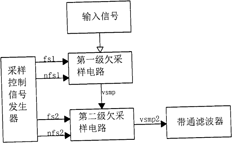
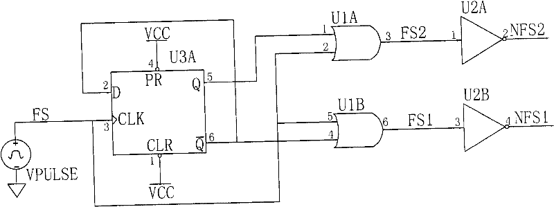
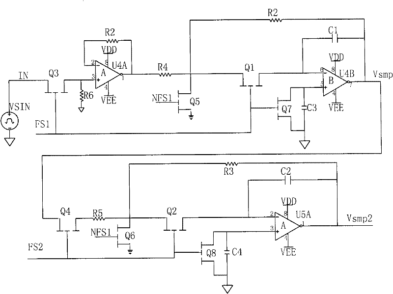
[0017] Refer to attached figure 1 to attach Figure 10 The undersampling frequency mixing circuit shown includes a sampling control signal generator, a first-stage under-sampling circuit, a second-stage under-sampling circuit, and a band-pass filter. The first output terminal of the sampling control signal generator is connected to the first The control signal input terminal of the first-stage under-sampling circuit, the second output end of the sampling control signal generator is connected to the control signal input end of the second-stage under-sampling circuit, and the signal output terminal vsmp1 of the first-stage under-sampling circuit is connected to the second-stage under-sampling circuit. The signal input terminal of the sampling circuit is connected, and the signal output terminal vsmp2 of the second stage undersampling circuit is connected with a bandpass filter; the sampling control signal generator includes a sampling frequency input terminal, a D flip-flop, an ...


PUM


Abstract

The invention relates to an undersampling mixer circuit. The undersampling mixer circuit comprises a sampling control signal generator, a first-stage undersampling circuit, a second-stage undersampling circuit and a band-pass filter, wherein the first output end of the sampling control signal generator is connected with the control signal input end of the first-stage undersampling circuit, the second output end of the sampling control signal generator is connected with the control signal input end of the second-stage undersampling circuit, the signal output end of the first-stage undersampling circuit is connected with the signal input end of the second-stage undersampling circuit, and the signal output end of the second-stage undersampling circuit is connected with the band-pass filter. The invention has the advantages of having low cost, being capable of converting high-frequency signals into low-frequency signals and being especially suitable for element detection devices.

Description

technical field [0001] The invention relates to the technical field of signal mixing, in particular to a mixing circuit for mixing high-frequency signals to low-frequency signals using the principle of under-sampling. Background technique [0002] In the high-frequency test circuit, the test signal generated after the high-frequency signal generated by the signal generator is loaded on the component under test is still a high-frequency signal. When these high-frequency signals are digitized, often due to the sampling frequency of the sampling chip If the sampling chip with high sampling frequency is selected, the cost will be very high, and a corresponding high-performance processing chip needs to be configured, which will eventually lead to extremely high cost or fundamental The detection of the component under test cannot be realized. Contents of the invention [0003] The purpose of the present invention is to provide an under-sampling frequency mixing circuit for the ...

Claims


Application Information

Patent Timeline
Patent Type & Authority Patents(China)
IPC IPC(8): H03D7/12
Inventor 陆文兴赵浩华朱华国汪刚高志齐
Owner CHANGZHOU TONGHUI ELECTRONICS
Why Eureka
Try Eureka