Method and device for realizing purpose of binding positions of CAN bus sensors

A CAN bus and sensor technology, which is applied in the field of CAN bus sensor position binding, can solve the problems of CAN bus sensor quantity limitation, limited application range and scalability, complex control system, etc., and achieve accurate binding and fast binding speed , Extensible effect

Active Publication Date: 2010-09-22
SANY HEAVY IND CO LTD (CN)
View PDF4 Cites 15 Cited by
  • Summary
  • Abstract
  • Description
  • Claims
  • Application Information

AI Technical Summary

Problems solved by technology

[0008] 1. The number of CAN bus sensors of the same type that can be connected is limited. Generally speaking, the number of CAN bus interfaces of the controller is between 1 and 2, which limits the use of the same type of CAN bus sensors in the system, especially For complex control systems
Moreover, due to the limitation of the number of CAN interfaces, its application range and scalability are very limited
[0009] 2. For complex control systems, multiple CAN bus networks are required, and each CAN bus network is independent, the wiring is complicated, and the reliability is not high

Method used


Image

  • Method and device for realizing purpose of binding positions of CAN bus sensors
  • Method and device for realizing purpose of binding positions of CAN bus sensors
  • Method and device for realizing purpose of binding positions of CAN bus sensors

Examples


Embodiment Construction

[0054] In order to enable those skilled in the art to better understand the solutions of the embodiments of the present invention, the embodiments of the present invention will be further described in detail below in conjunction with the drawings and implementations.

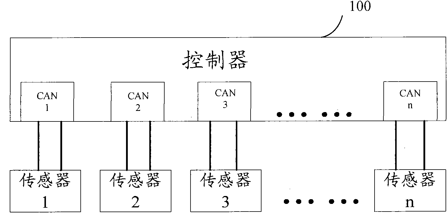
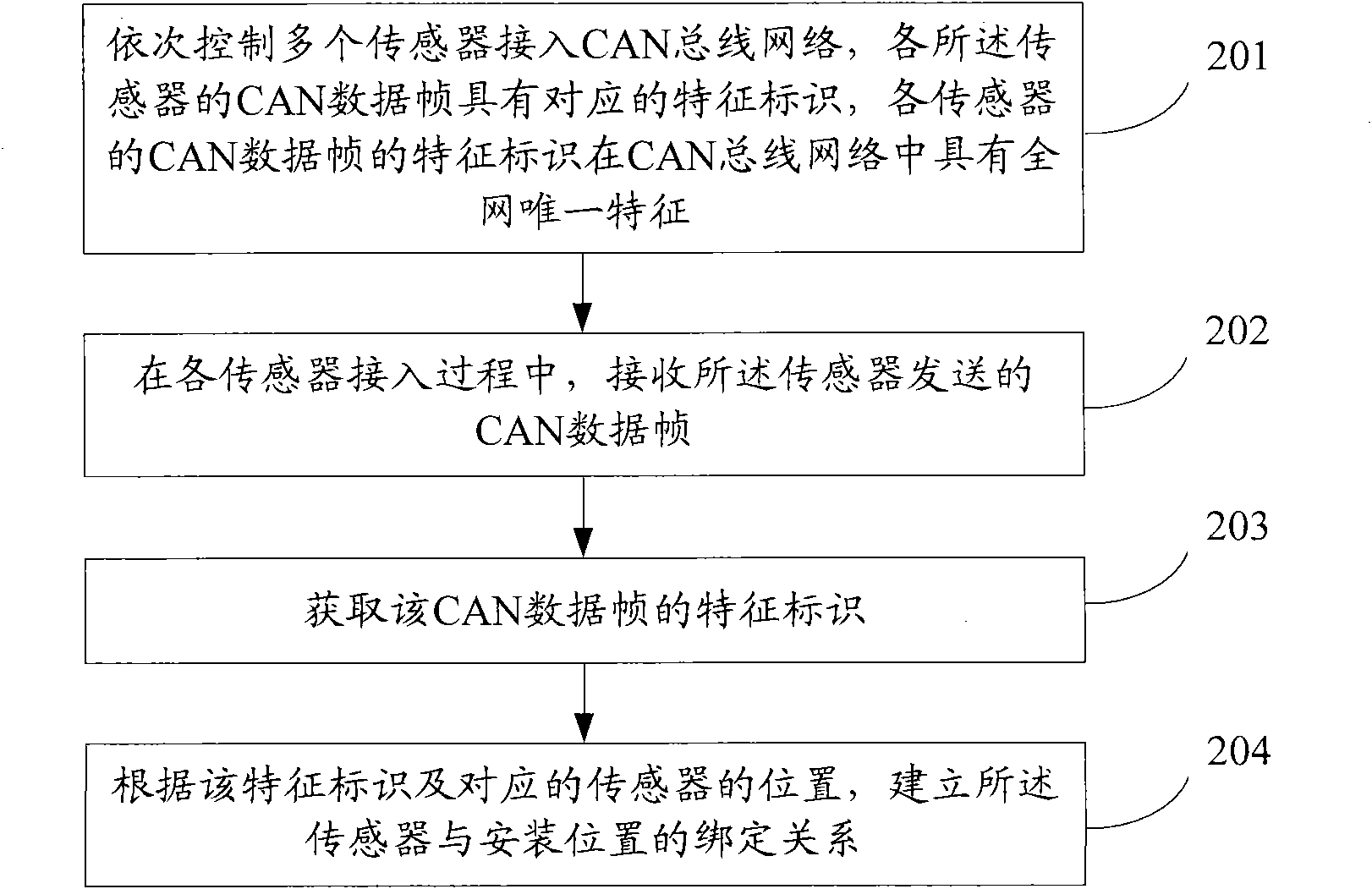
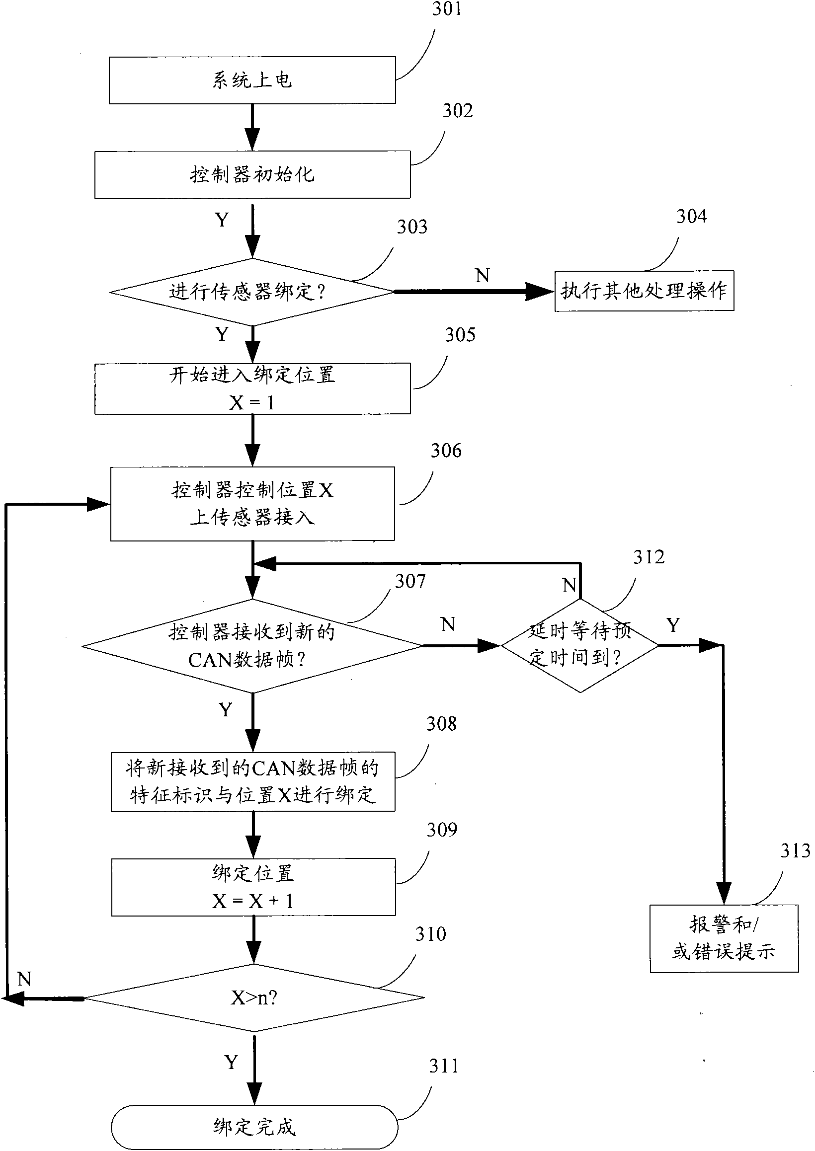
[0055]The embodiment of the present invention realizes the method and device for CAN bus sensor position binding, and for the same type and / or different types of sensors, sequentially controls each of the sensors to access the CAN bus network, and the CAN data frame of each of the sensors has a corresponding Feature identification, the feature identification of the CAN data frame of each sensor has the unique feature of the whole network in the CAN bus network; during the access process of each sensor, receive the CAN data frame sent by the sensor; obtain the feature identification of the CAN data frame; According to the feature identifier and the corresponding sensor location, a binding relationship between the ...


PUM


Abstract

The invention relates to the technical field of sensors, in particular discloses a method and a device for realizing the purpose of binding the positions of CAN bus sensors. The method comprises the following steps: sequentially controlling a plurality of sensors to be accessed to a CAN bus network, wherein the CAN data frame of each sensor has corresponding characteristic identification, and the characteristic identification of the CAN data frame of each sensor is unique in the whole CAN bus network; receiving the CAN data frame sent by each sensor in the accessing process of each sensor; acquiring the characteristic identification of each CAN data frame; and establishing the binding relation between each sensor and each installing position corresponding to the currently binding position according to each characteristic identification. The invention can be used for automatically establishing binding relation between a plurality of CAN bus sensors and each of installing positions on one CAN bus, thereby meeting the requirement for applying CAN bus sensors in a complex control system.

Description

technical field [0001] The invention relates to the technical field of sensors, in particular to a method and device for realizing the position binding of CAN (Controller Area Network, Controller Area Network) bus sensors. Background technique [0002] With the development of science and technology, people put forward higher and higher requirements for equipment. Nowadays, there is no longer a big gap in the realization of the basic functions of equipment. The competition between equipment is more and more reflected in its own intelligent control level. up and down. The improvement of equipment intelligence makes the application of sensors more and more in-depth. [0003] At present, various smart sensors have gradually entered people's sight. The so-called smart sensor refers to a sensor with a microprocessor, which has the functions of information detection and information processing. The biggest feature of smart sensors is to organically integrate the function of senso...

Claims


Application Information

Patent Timeline
Patent Type & Authority Applications(China)
IPC IPC(8): H04L12/40H04L12/26
Inventor 周翔周继辉罗诗风
Owner SANY HEAVY IND CO LTD (CN)
Why Eureka
Try Eureka