
Heating cartridge for thermostatic element and method for manufacturing same, as well as thermostatic valve comprising such a cartridge

A technology for constant temperature elements and heating cylinders, applied in heating elements, temperature control, engine elements, etc., can solve problems such as difficult implementation and unacceptable molding costs

Inactive Publication Date: 2010-09-22
VERNET SA
View PDF5 Cites 6 Cited by
  • Summary
  • Abstract
  • Description
  • Claims
  • Application Information

AI Technical Summary

Problems solved by technology

This revolutionary solution proved to be practically difficult to implement, as it required an injection mold that was adapted simultaneously to every possible shape and size of the tube and to the overall axial dimension of the heating cartridge that one wished to obtain
Therefore the molding cost to conform to the different geometries of the heating cartridge becomes unacceptable

Method used


Image

  • Heating cartridge for thermostatic element and method for manufacturing same, as well as thermostatic valve comprising such a cartridge
  • Heating cartridge for thermostatic element and method for manufacturing same, as well as thermostatic valve comprising such a cartridge
  • Heating cartridge for thermostatic element and method for manufacturing same, as well as thermostatic valve comprising such a cartridge

Examples


Embodiment Construction

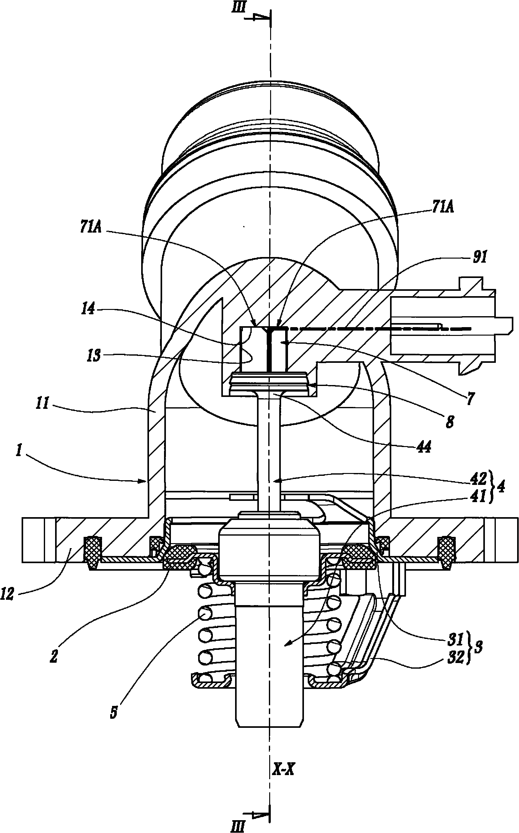
[0034] figure 1 Shown is a thermostatic valve comprising a housing 1 designed to circulate in it a fluid regulated by the other parts of the valve, in particular a cooling liquid when the valve belongs to a cooling circuit for a heat engine . The housing 1 comprises a tubular body 11 here of curved overall shape, part of which belongs to figure 1 The cutting plane is centered on the axis X-X and extends in length. During use, the aforementioned fluid flows through the body 11 between the two longitudinal ends while being regulated by the spacer plug 2, here at the end of the part of the body 11 centered on the axis X-X, the spacer plug 2 is centered on the axis X-X and can translate along this axis: if figure 1 As shown, when the plug is pushed in a sealable manner against the valve seat 31 defined by the rigid bracket 3 fixedly connected to the splint 12 of the housing 1, the flow of fluid is interrupted; and when When the isolation plug 2 is separated from the valve seat...


PUM


Abstract

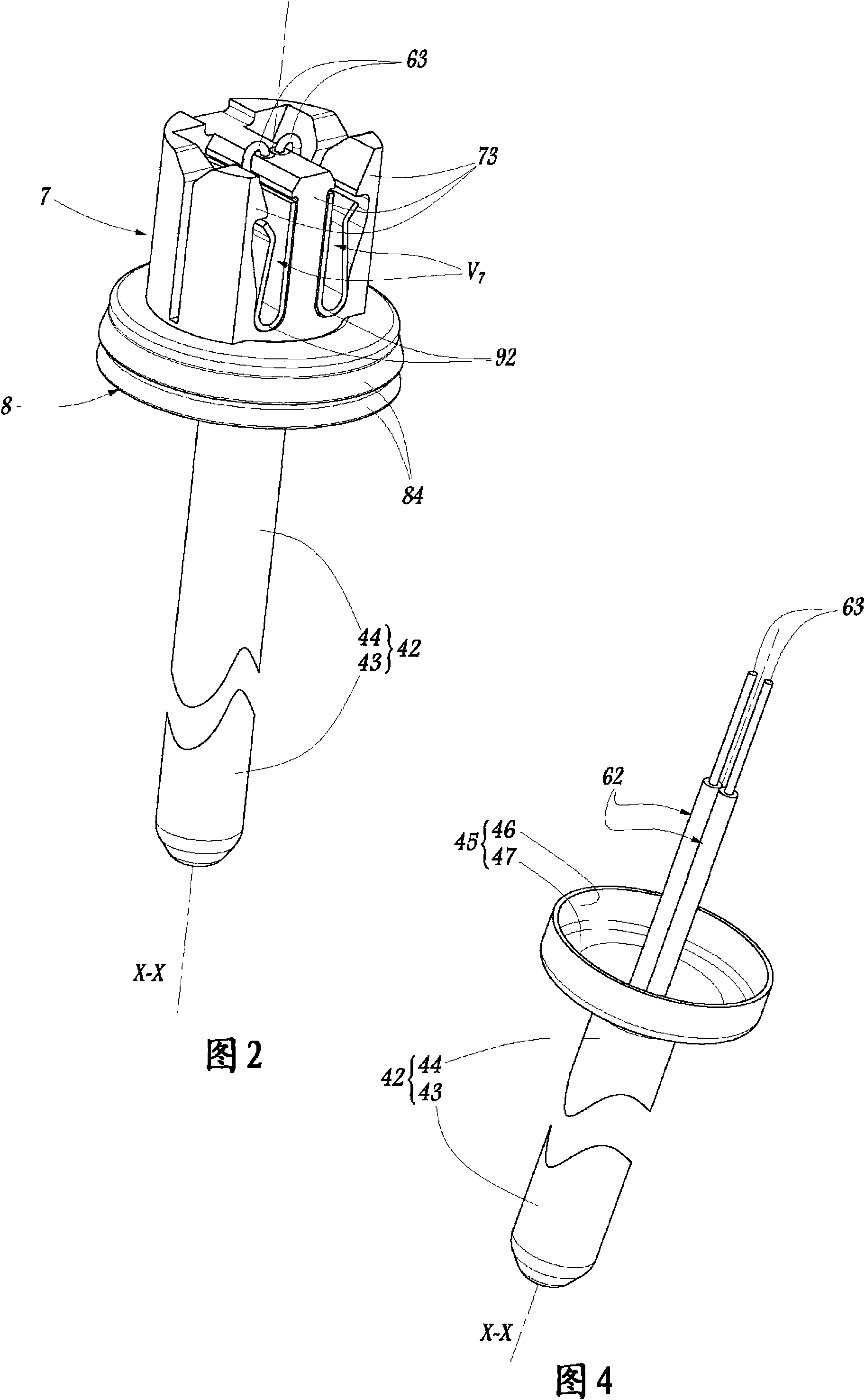
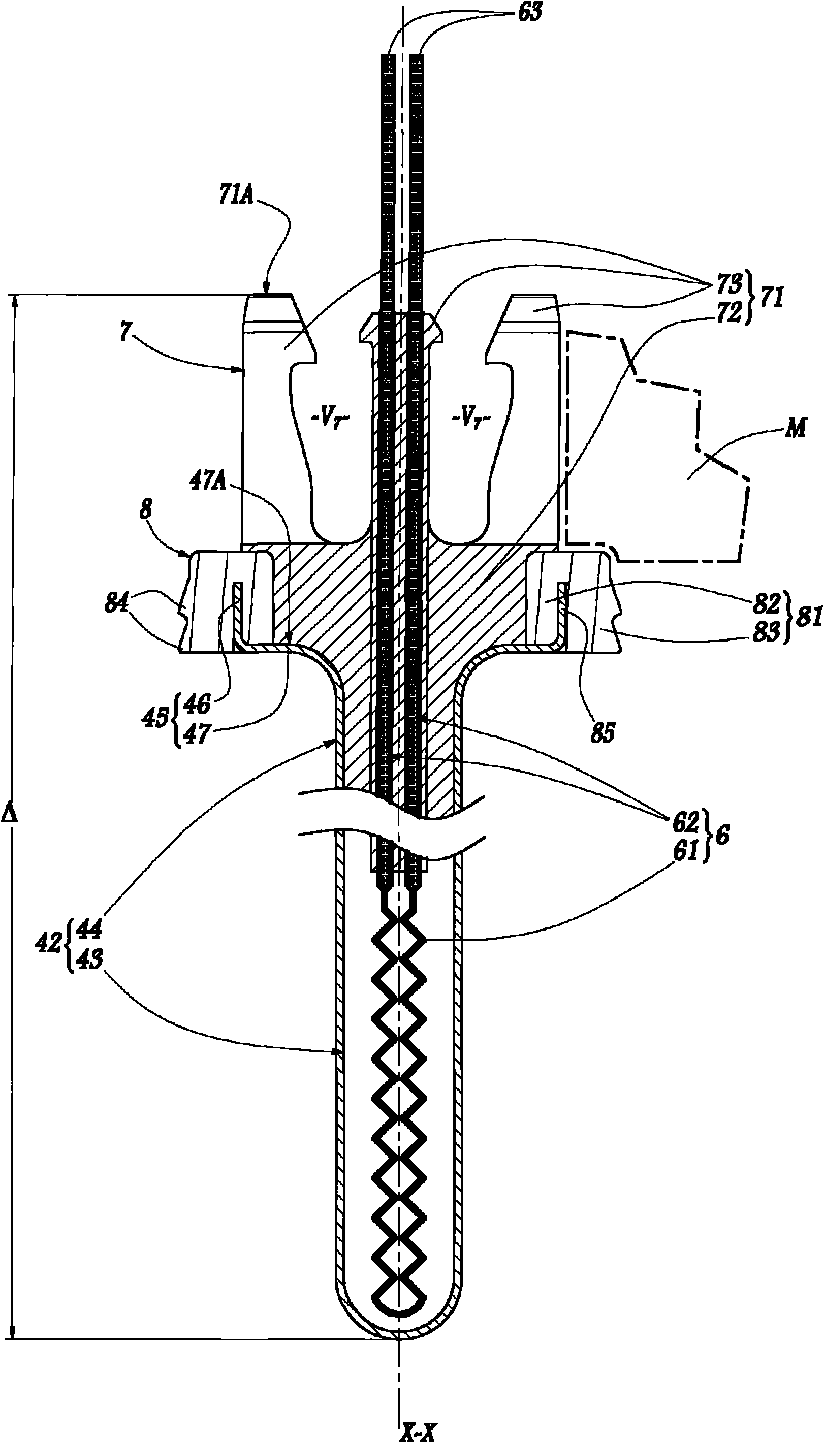
This heating cartridge includes a thermally conductive tube (42) to be immersed in a thermo-expandable substance of the thermostatic element, electric heating means (6) arranged inside the tube, and a base (7) made of a plastic substance, integral with a terminal longitudinal portion (44) of the tube and adapted to support the electric connection between the heating means and an external current source. In order to make the connection between the base and the tube both resistant and precisely adaptable to various heating cartridge geometries, and to do so economically, the terminal portion of the tube comprises an outwardly flared free end (45), which extends protruding both radially and axially from the rest of the terminal portion and in which the base is attached by overmolding.

Description

technical field [0001] The invention relates to a heating cartridge for a thermostatic element and to a method for producing such a cartridge. The invention also relates to a thermostatic valve comprising such a heating cartridge. Background technique [0002] In many applications in the field of fluidics, especially for the cooling of vehicle heat engines, thermostatic valves are used to distribute the fluid into different circulation channels according to the temperature of the fluid. These valves are called thermostatic valves because the movement of their internal plug is controlled by a thermostatic element, an element consisting of a cup containing a thermally expandable substance and a piston capable of thermally expanding During the expansion of the substance the heat-expandable substance is displaced in a sliding manner relative to the cup. [0003] In order to dispense the fluid according to other parameters, especially according to conditions external to the val...

Claims


Application Information

Patent Timeline
Patent Type & Authority Applications(China)
IPC IPC(8): H05B3/40H05B3/06F16K31/64
CPCH05B3/06H05B3/80G05D23/022Y10T29/49083
Inventor 尼古拉斯·波蒂蒂埃里·马罗
Owner VERNET SA
Learn More