Turbomolecular pump

A technology of turbomolecular pump and pump casing, which is applied in the direction of pump, pump control, pump components, etc., can solve the problems of complex structure design of turbomolecular pump, and achieve the effect of high rotatability.

Inactive Publication Date: 2010-09-22
OERLIKON LEYBOLD VACUUM
View PDF1 Cites 7 Cited by
  • Summary
  • Abstract
  • Description
  • Claims
  • Application Information

AI Technical Summary

Problems solved by technology

The structural design of this tu...

Method used


Image

  • Turbomolecular pump
  • Turbomolecular pump
  • Turbomolecular pump

Examples


Embodiment Construction

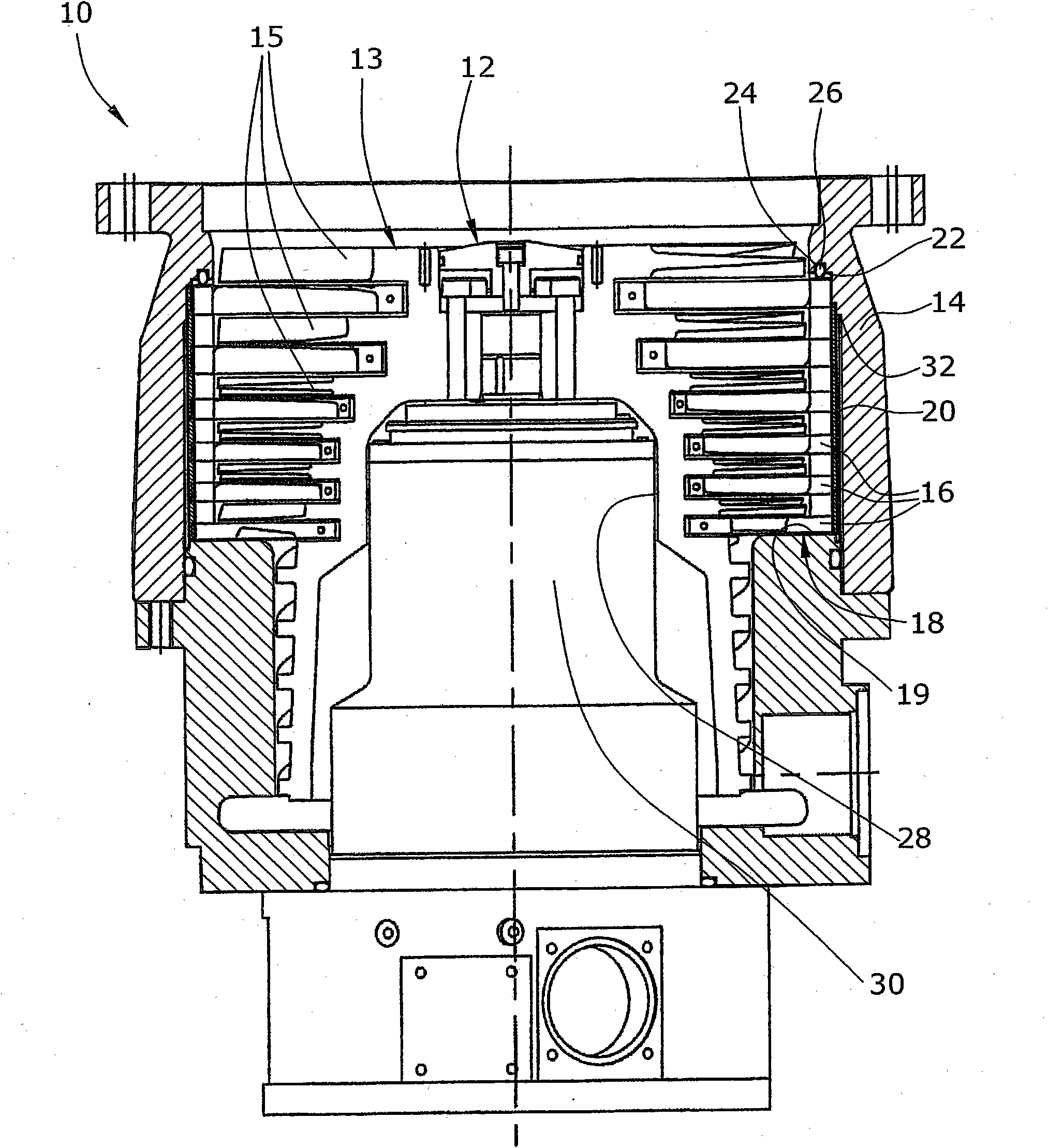
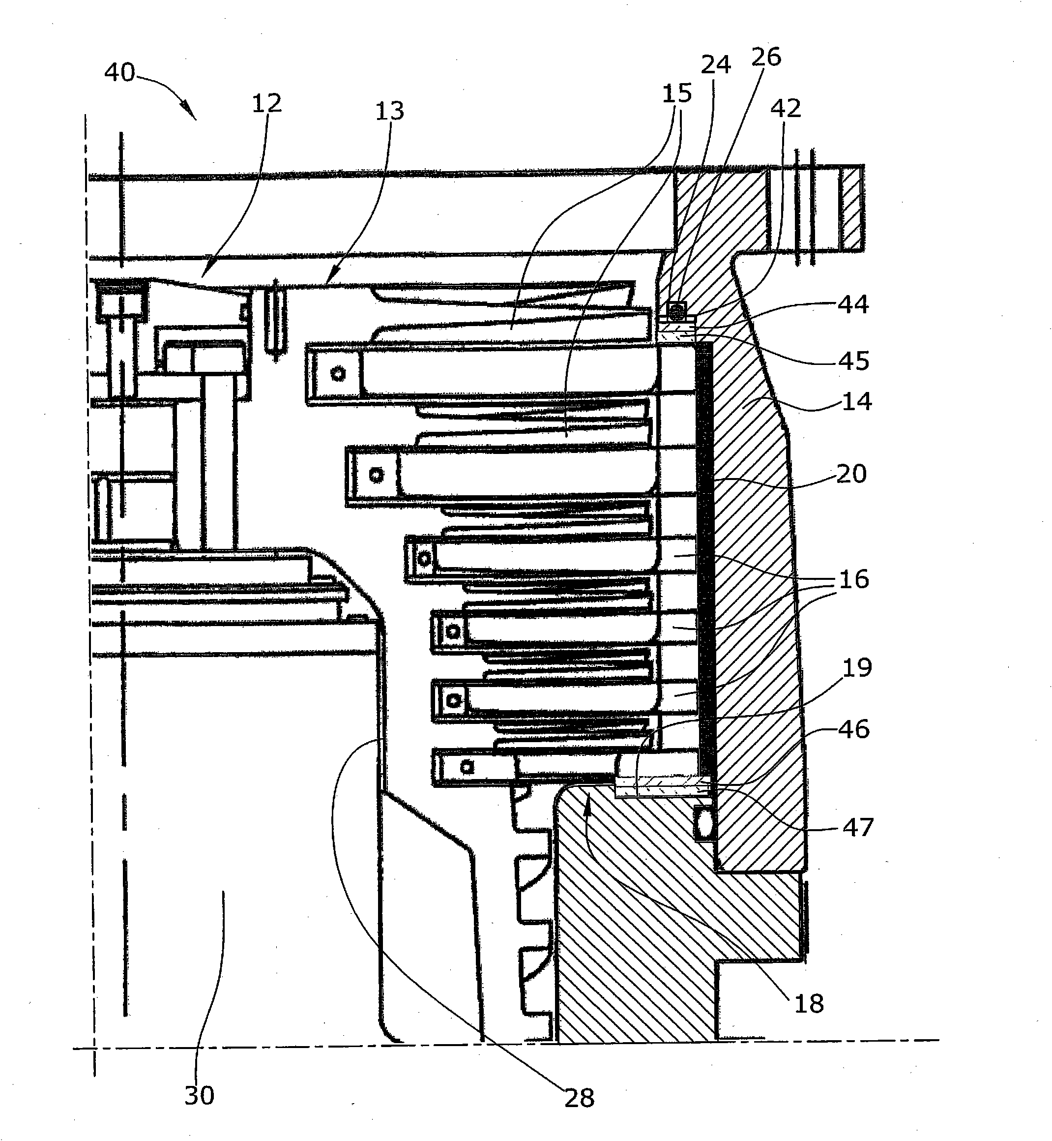
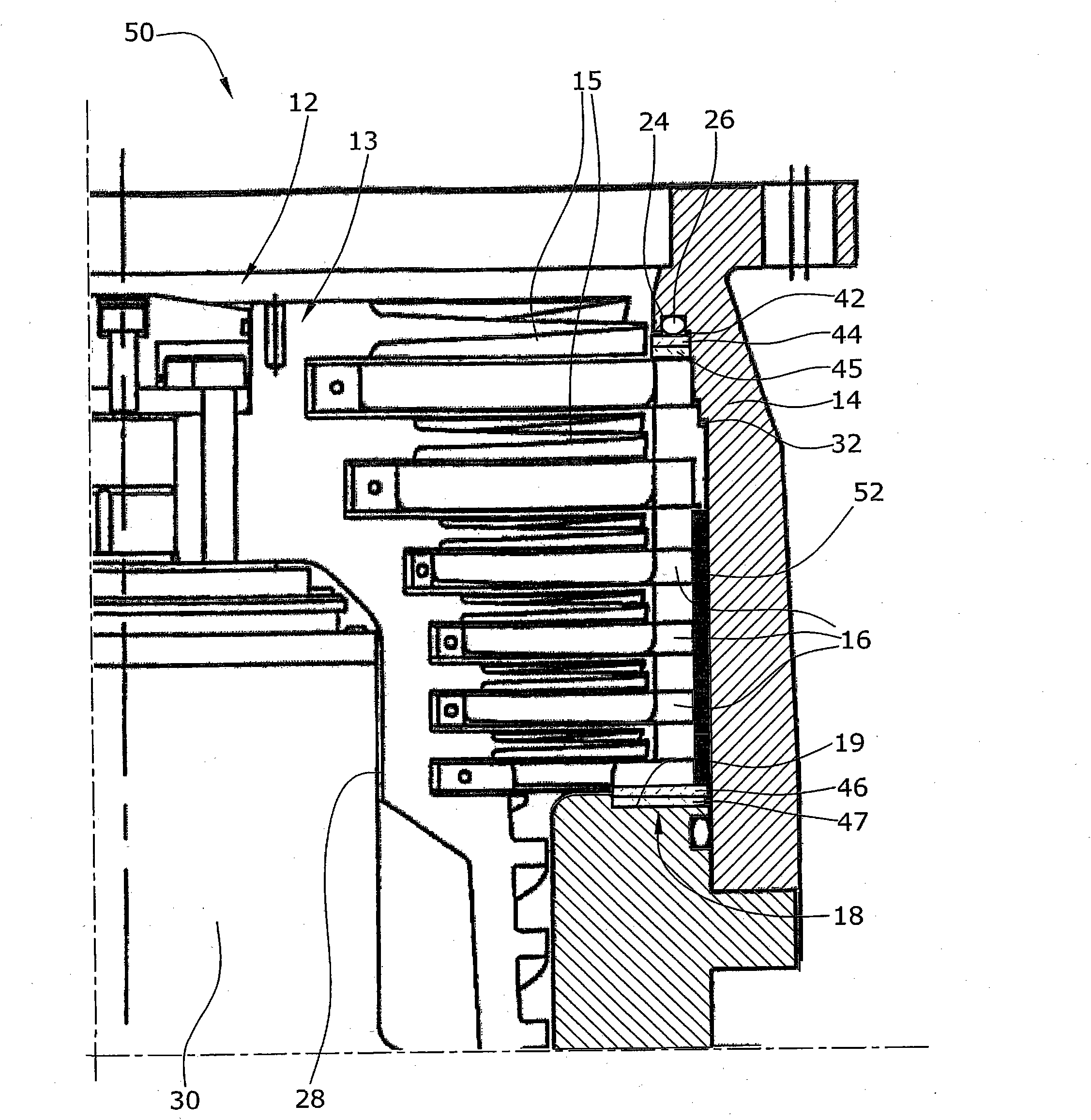
[0019] Figure 1-3 is a longitudinal sectional view of a respective turbomolecular pump 10 , 40 and 50 provided with a rotor 12 comprising a pump rotor 13 arranged to rotate on a pump housing 14 . The pump rotor 13 includes a plurality of rotor blade disks 15 . Extending into the axial gap between each pair of said blade disks is a respective one of the annular stator blade disks 16 . In this embodiment, six rotor blade disks 15 and six stator blade disks 16 are provided.

[0020] The axially assembled stator blade disks 16 together form an annular disk pack 18 . On the pressure side, the annular disk pack 18 is supported on a corresponding annular abutment surface 19 arranged in a transverse plane. The other axial end of the annular disk pack 18 is not arranged in direct axial abutment on the pump housing. Between the pump housing 14 and the annular disc pack 18 an axial gap 22 is provided such that the annular disc pack 18 is generally adapted for axial displacement with...


PUM


Abstract

The invention relates to a turbomolecular pump (10) having a pump housing (14) and multiple separate stator blade ring discs (16), which form a ring disc packet (18) together. A cylindrical friction bush (20) is disposed directly between the ring disc packet (18) and the pump housing (14). An axial gap (22) is provided axially between the ring disc packet (18) and the pump housing (14), so the ring disc packet (18) can be rotated.

Description

technical field [0001] The invention relates to a turbomolecular pump, which comprises a pump casing and a plurality of individual annular stator vane disks, and the plurality of individual annular stator blade disks are combined to form an annular disk group. Background technique [0002] Turbomolecular pumps normally work at an operating speed of tens of thousands of rpm. Consequently, the rotor, when operating at its operating speed, has a high kinetic energy which would cause considerable damage if the rotor were to collide or burst. In fact, these destructive forces may be so great that the pump housing may be damaged, resulting in extensive damage to the equipment, risk of bodily contact and eventual risk of fatal injury. [0003] According to EP 1 030 062 A2 a turbomolecular pump is known in which the annular disk pack is held by a separate annular disk housing. The annular disk housing is arranged to be rotatable relative to the pump housing. Between the annular d...

Claims


Application Information

Patent Timeline
IPC IPC(8): F04D19/04F04D27/02
CPCF04D19/042F04D27/008F04D29/522
Inventor 海因里希·恩伦德尔
Owner OERLIKON LEYBOLD VACUUM
Why Eureka
Try Eureka