Flue gas mercury removal device

A technology for mercury removal and flue gas removal, applied in separation methods, dispersed particle separation, chemical instruments and methods, etc., can solve the problems of low utilization rate, low capacity, and high cost of activated carbon, and achieve low implementation cost, high mercury removal efficiency, and high efficiency. The effect of convenient maintenance

Inactive Publication Date: 2012-08-29
CHONGQING UNIV
View PDF3 Cites 2 Cited by
  • Summary
  • Abstract
  • Description
  • Claims
  • Application Information

AI Technical Summary

Problems solved by technology

Spray powdered activated carbon (PAC) into the flue gas. After the powdered activated carbon absorbs mercury, it is removed by the downstream dust collector (such as electrostatic precipitator, bag filter), but the activated carbon is mixed with fly ash and cannot be regenerated.
Due to the problems of low capacity, poor mixing, and low thermodynamic stability, and the low utilization rate and large consumption of activated carbon, the cost of directly using activated carbon adsorption is too high
The U.S. Department of Energy estimates that to achieve a mercury removal rate of 90%, the cost of removing 0.45kg of mercury is (2.5-7.0)×10 4 Dollar, Coal Power Plants Hard to Afford

Method used


Image

  • Flue gas mercury removal device
  • Flue gas mercury removal device

Examples


specific Embodiment approach 1

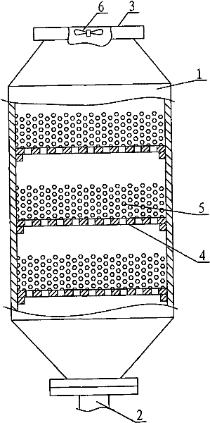
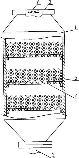
[0019] Specific implementation mode one: as figure 1 As shown, a flue gas mercury removal device includes a reactor shell 1, the lower part of the reactor shell 1 is provided with an air inlet 2, and the upper part is provided with an air outlet 3, wherein the inner cavity of the reactor shell 1 is Three layers of porous support plates 4 are arranged between the air port 2 and the air outlet 3 , and each support plate 4 is provided with an adsorption packing layer 5 . During implementation, described air outlet 3 places are provided with aspirator 6, and during specific implementation, described aspirator 6 also can be arranged in the pipeline that communicates with air outlet; The adsorption filler in described adsorption filler layer 5 is composed of activated carbon particles .

[0020] In order to verify the technical solution of this embodiment and optimize the specific parameter settings, the applicant, based on the above-mentioned device structure, changed the porous s...

specific Embodiment approach 2

[0027]Embodiment 2: In Embodiment 2, on the basis of Embodiment 1, the adopted adsorption filler is replaced by a new type of adsorption filler independently developed by the applicant, and the rest of the implementation conditions remain unchanged. The new adsorption filler includes the following preparation steps: using 72% of fly ash, 7% of calcium oxide, 3% of sodium bromide, 12% of Hunan clay, 3% of polyethylene, and 3% of rice husk to mix, mix Add water and mix thoroughly, then extrude and granulate to form granules with a particle diameter of 30-50mm, and then sinter and shape at a high temperature of 900-1100°C.

[0028] First, in order to verify and optimize the mercury absorption effect of the new adsorption filler, the applicant conducted a large number of tests to optimize the parameters such as the molding particle size, sintering temperature, and sintering holding time during the preparation process of the above-mentioned new adsorption filler. During the experim...


PUM


Abstract

The invention discloses a flue gas mercury removal device, comprising a reactor casing, the lower part of which is provided with a gas inlet and the upper part of which is provided with a gas outlet. The flue gas mercury removal device is characterized in that, porous support plates at three layers are arranged between the gas inlet and the gas outlet of an inner cavity of the reactor casing, andeach support plate is provided with an adsorptive filler layer. Compared with the prior art, the flue gas mercury removal device has the advantages of high mercury removal efficiency and convenient implementation cost; in addition, the porous support plates at three layers are arranged, so a temporary maintenance platform during maintenance is not required and operational maintenance staff can stand on a flue gas rectifier plate to maintain and replace internal parts, thus the device also has the advantage of convenient maintenance.

Description

technical field [0001] The invention relates to the technical field of mercury removal from flue gas, in particular to a reaction device for mercury removal from flue gas. Background technique [0002] Domestic flue gas mercury removal technology research mainly focuses on the development of high-efficiency adsorbents and how to effectively use existing pollution control equipment to improve mercury removal efficiency and take the road of compound pollution control. [0003] Flue gas desulfurization units and selective catalytic reduction equipment can capture mercury well. The wet desulfurization device can remove 80%-95% of the oxidized mercury in the flue gas, but the capture effect of the gaseous mercury insoluble in water is not significant, and it is necessary to use an oxidant to oxidize the elemental mercury first, which has secondary pollution and production issues such as higher costs. The Selective Catalytic Reduction (SCR) device can reduce Hg while reducing NO...

Claims


Application Information

Patent Timeline
Patent Type & Authority Patents(China)
IPC IPC(8): B01D53/04
Inventor 刘清才高威杨剑董凌燕鹿存房徐敏人文娟郑慧敏刘成伟
Owner CHONGQING UNIV
Why Eureka
Try Eureka