Air conditioner device

An air-conditioning device and air-conditioning technology, which are applied in air-conditioning systems, space heating and ventilation, separation methods, etc., can solve the problems of large-scale and thickening of the device, improve the electric field density, increase the generation amount, and realize miniaturization. · Thinning effect

Active Publication Date: 2010-09-29
DAIKIN IND LTD
View PDF1 Cites 0 Cited by
  • Summary
  • Abstract
  • Description
  • Claims
  • Application Information

AI Technical Summary

Problems solved by technology

On the other hand, as shown in the air conditioner disclosed in Patent Document 1, when a corona discharge unit is mounted in the device, a space for accommodating the corona discharge unit is required, and the required storage space is increased. From the point of view, the device will be enlarged and thickened

Method used


Image

  • Air conditioner device
  • Air conditioner device
  • Air conditioner device

Examples


Deformed example 2

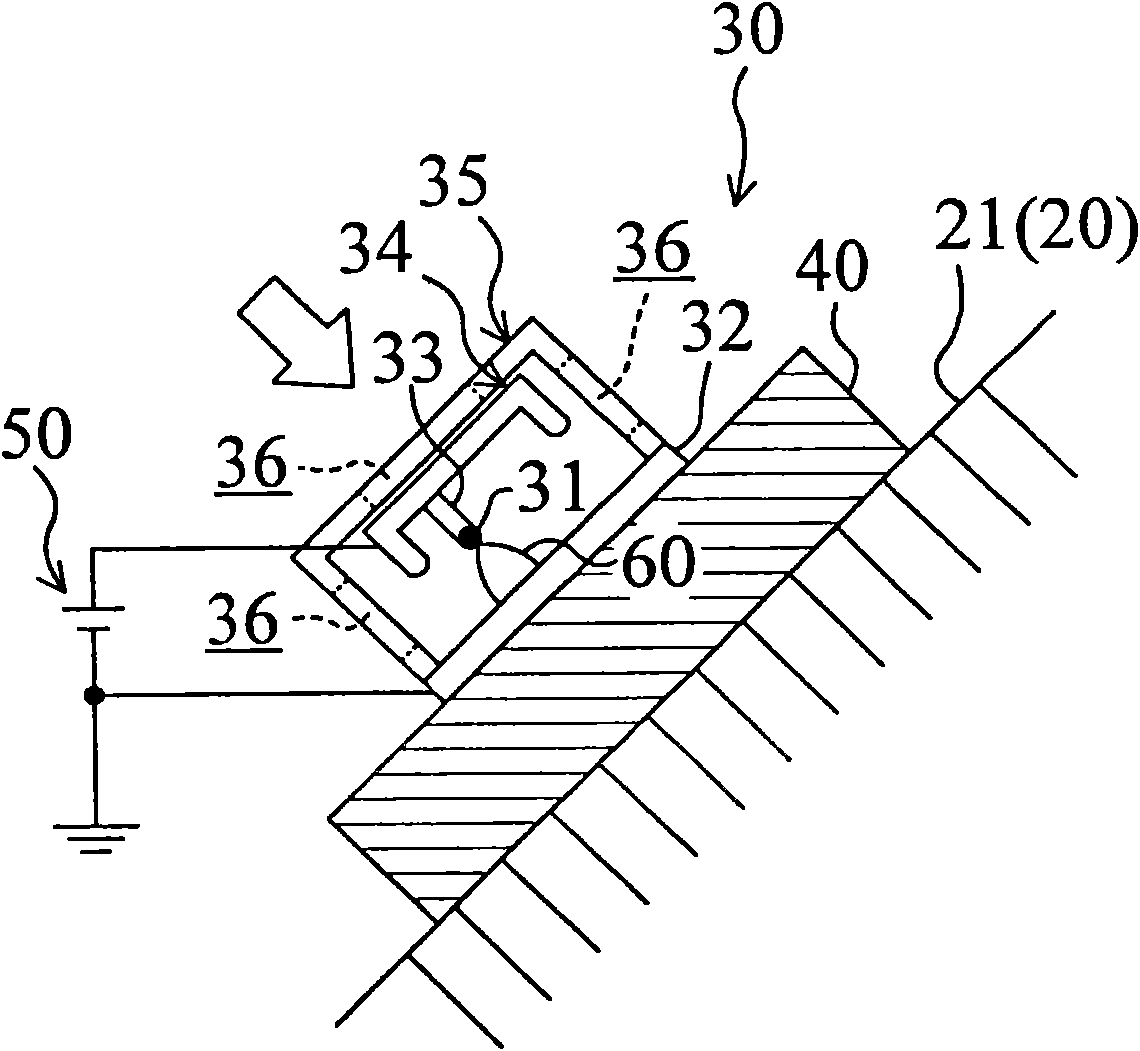
[0085] in such as Figure 5 In the discharge unit ( 30 ) shown in Modification 2, a needle-shaped discharge electrode ( 31 ) is supported on one side of a support plate ( 33 ) whose vertical section is "L"-shaped. The discharge electrode (31) is composed of a rod-shaped trunk and a conical protrusion formed at the tip of the trunk. On the other hand, the counter electrode (32) is arranged in the air passage (15) substantially parallel to the discharge electrode (31). In addition, the discharge electrode (31) and the counter electrode (32) are perpendicular to the air flow direction and arranged along the air inflow surface of the heat exchanger (20), not shown, as in the above-mentioned embodiment. Then, when a voltage is applied from a DC power supply (50) to both electrodes (31, 32), streamer discharge (60) develops from the tip of the protrusion of the discharge electrode (31) to the counter electrode (32).

[0086] Also in this modification 2, since the streamer discharg...

Deformed example 3

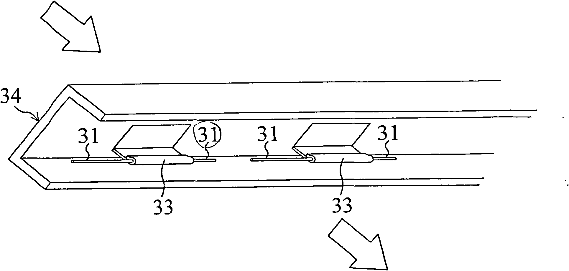
[0088] Image 6 The discharge unit ( 30 ) of the third modification shown is the same as the above embodiment, including an insulating barrier ( 35 ), a discharge base ( 34 ) and a rod-shaped discharge electrode ( 31 ). On the other hand, in this third modification, different from the above-mentioned embodiment, there is no plate-shaped counter electrode (32), and the top end of the discharge electrode (31) faces the heat exchanger (20). The heat exchanger (20) is mainly composed of conductive aluminum, and is electrically connected to the negative side (ground side) of the DC power supply (50). Furthermore, the heat exchanger (20) is configured to also serve as the counter electrode (32) of the above-mentioned embodiment. That is, once a voltage is applied from the DC power supply (50) to the discharge electrode (31) and the heat exchanger (20), a streamer discharge is developed from the top of the rod-shaped discharge electrode (31) to the surface of the heat exchanger (20)...


PUM


Abstract

The invention provides an air conditioner device, which comprises an air path through which the processed air flows and an air conditioning component for regulating the air flowed in the air path. The air conditioner device is characterized in that an electric discharge unit for performing streamer discharge is arranged in the air path. The electric discharge unit comprises a stick-like discharge electrode which is linear or bar-shaped and a plate-like opposed electrode for performing streamer discharge from the top and drawing back the top following the process of the streamer discharge, wherein the opposite electrodes are arranged orthogonal to the discharge electrodes by keeping a distance between the irradiating electrode and the opposite electrode.

Description

[0001] This case is a divisional application of the patent application with the application date of February 20, 2006, the application number 200680005599.1 (the international application number is PCT / JP2006 / 302941), and the invention name is "air-conditioning device". technical field [0002] The invention relates to an air conditioner for conditioning the air to be processed, in particular to an air conditioner for purifying the air to be processed. Background technique [0003] Conventionally, air-conditioning apparatuses for air-conditioning indoor spaces such as general households have been known. Among such air conditioners, those having an air cleaning function are also widely known. [0004] For example, the air conditioner disclosed in Patent Document 1 is a so-called wall-mounted room air conditioner provided with an air cleaning function. In this air conditioner, an air passage for treated air is formed in a cabinet. The air passage is provided with a corona di...

Claims


Application Information

Patent Timeline
Patent Type & Authority Applications(China)
IPC IPC(8): F24F1/00B03C3/02B03C3/40A61L9/00A61L9/16A61L9/22B01D53/86B01J19/08F24F1/0063F24F1/0076
CPCF24F3/166B03C3/025F24F2003/1682F24F2003/1621B03C3/383B01D53/32F24F2003/1635F24F2001/0048F24F1/0007A61L9/16A61L9/22B03C3/455B01D2259/818B03C2201/10F24F1/0057F24F8/194F24F8/15F24F8/30F24F8/192F24F1/0076F24F1/0063F24F1/00A61L9/00
Inventor 田中利夫香川谦吉茂木完治秋山龙司
Owner DAIKIN IND LTD
Why Eureka
Try Eureka