
Construction paying off method for determining boundary point of side slope of subgrade on terrain line

A technology for slopes and boundary points, which is used in infrastructure engineering, excavation, measuring devices, etc., and can solve problems such as large errors in filling slope toe lines, increasing engineering volume, and destroying the natural environment on the surface.

Active Publication Date: 2010-09-29
华邦建投集团股份有限公司
View PDF4 Cites 21 Cited by
  • Summary
  • Abstract
  • Description
  • Claims
  • Application Information

AI Technical Summary

Problems solved by technology

In this way, the position of the stakeout boundary point is not necessarily on the feature point of the terrain, so the error of the cut groove line or fill slope foot line formed by connecting the boundary points is very large, which not only affects the construction quality of the slope, but also due to over-excavation, over-excavation, etc. Filling increases the amount of work and destroys the natural environment on the surface

Method used


Image

  • Construction paying off method for determining boundary point of side slope of subgrade on terrain line
  • Construction paying off method for determining boundary point of side slope of subgrade on terrain line
  • Construction paying off method for determining boundary point of side slope of subgrade on terrain line

Examples


Embodiment Construction

[0035] 1 Determine the midline mileage and offset distance corresponding to the slope test point

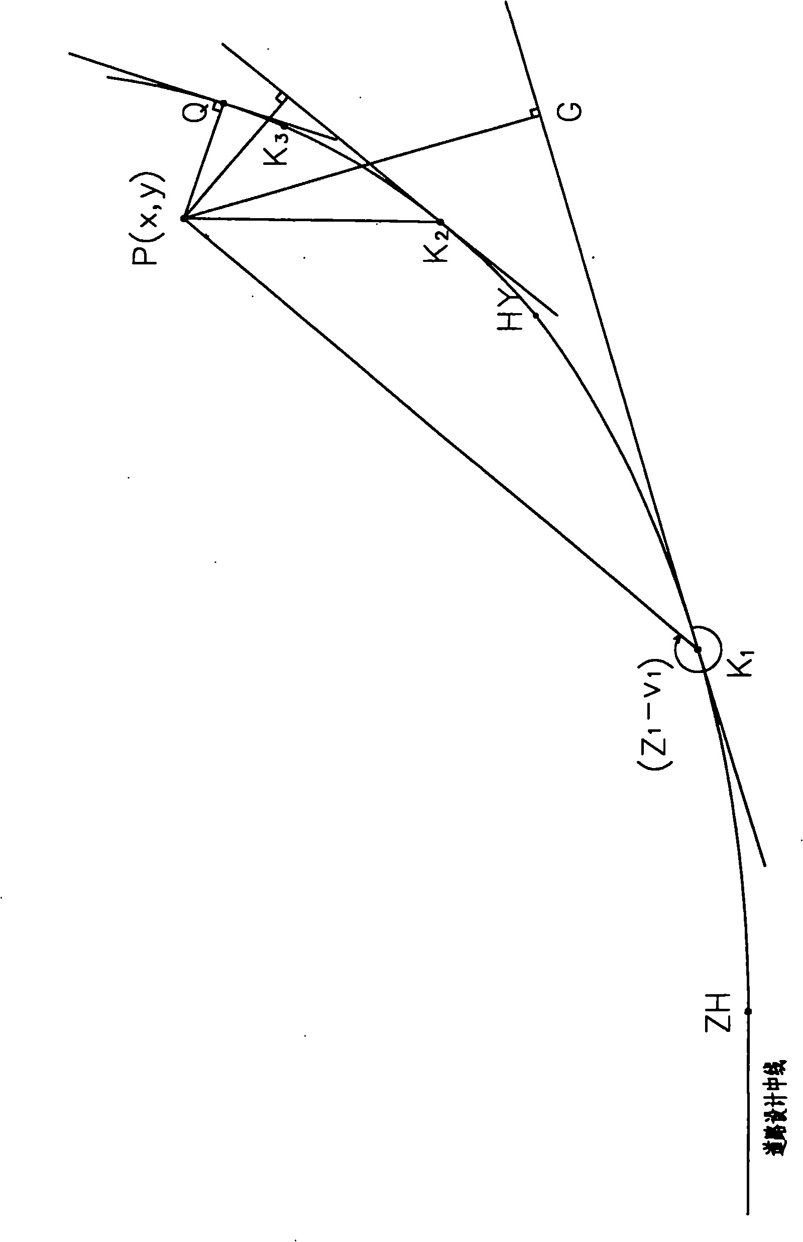
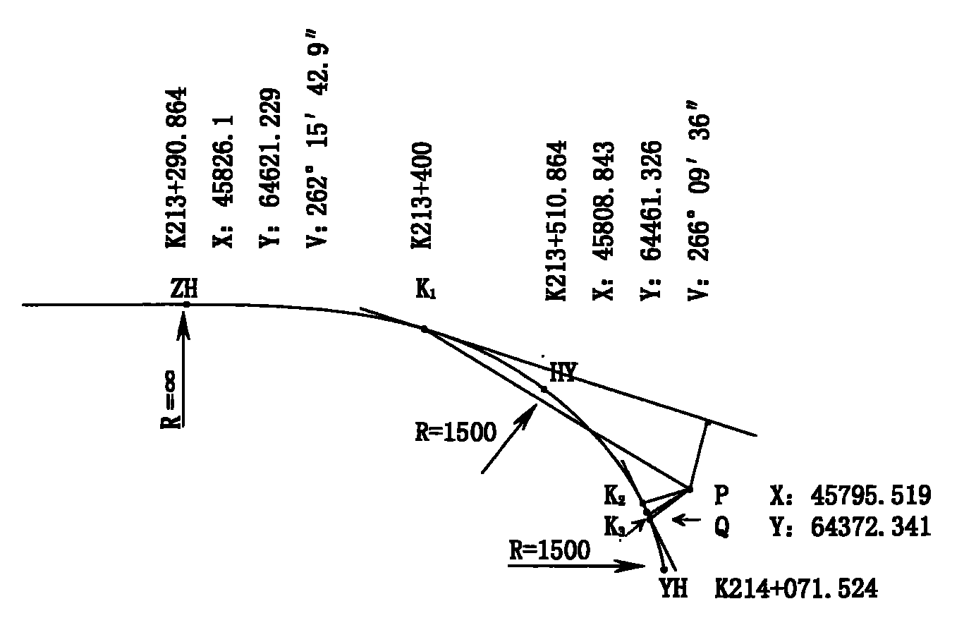
[0036] Such as image 3 A part of the centerline of a road design shown, including three types of curves: straight line, transitional curve and circular curve. At the construction site, use the total station to measure the coordinates of the slope test point P located on the ground line: X: 45795.519, Y: 64372.341, H: 1509.030.

[0037] 1.1 Set the midline mileage reference point corresponding to point P

[0038] According to the impression of the surveyors, point P should be around K12+400, so set K 1 Set the first reference point K as the point mileage 1 The mileage is: 213+400. Once the midline mileage is determined, it can be figure 2 K 1 Located on the transitional curve, take the design elements of the transitional curve: coordinates of the starting point of the curve A(45826.1, 64621.229), ρ A =0, L=220,V A =262°15′42.9″, calculate K on behalf of formulas (1), (...


PUM


Abstract

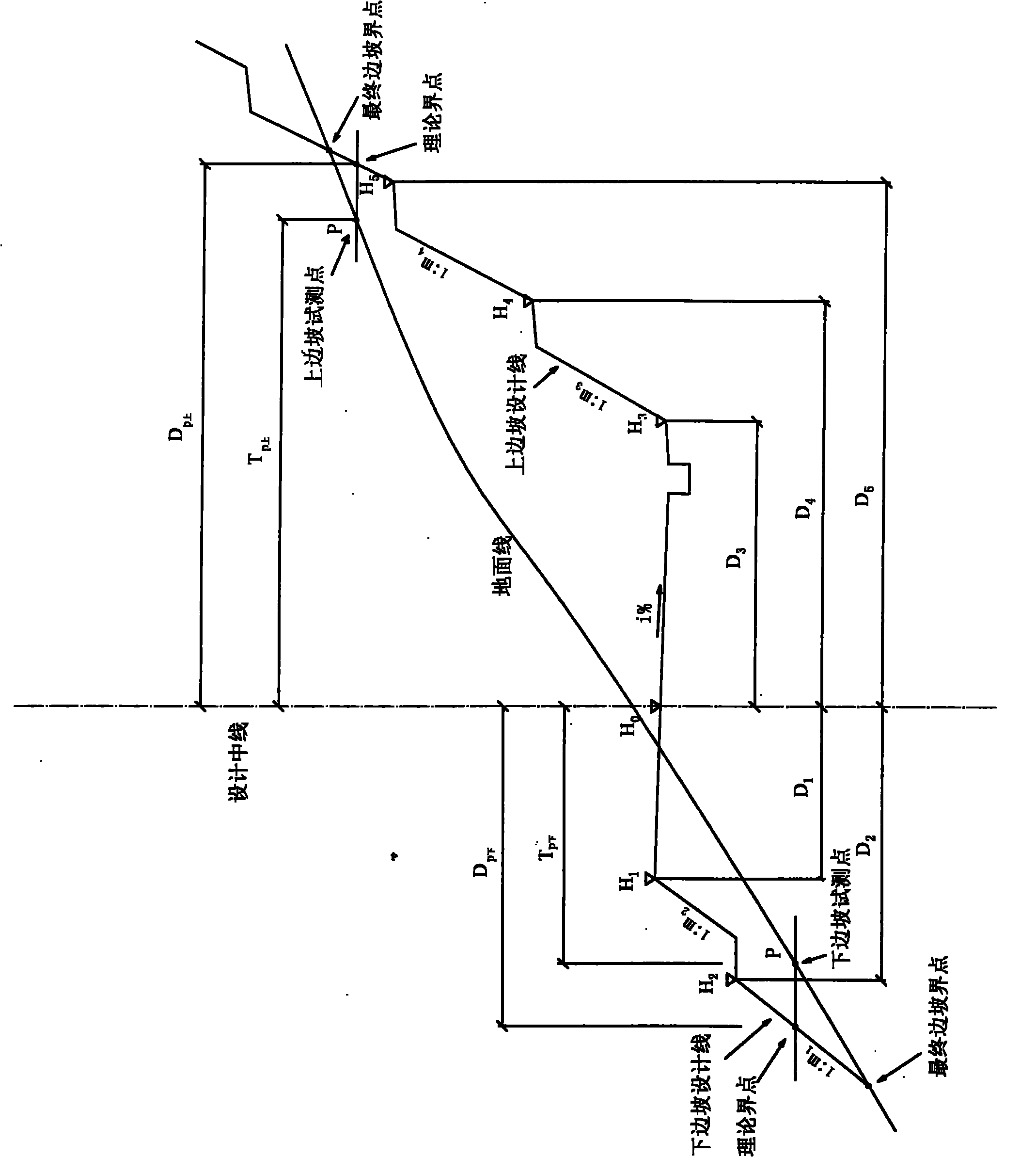
The invention provides a construction paying off method for determining the boundary point of a side slope of a subgrade on a terrain line, which can improve the paying off efficiency of the boundary point of the side slope of the subgrade and meet the requirement for the construction precision of the side slope of the subgrade, and can be extensively completed by testing an intervisible part of any survey station arranged outside the design center line of a road. The method comprises the following steps of: setting a mileage reference point on the center line of a road, evaluating the shortest distance between the side point of the center line and the horizontal curve of the road by using the method of uniform approach so as to determine the vertical distance and the foot-point mileage between the slope point subjected to on-site pretesting and the design center line of the road in a plane; calculating the theoretical horizontal distance between a crossover point of an elevation surface on which the pretesting point is positioned and the design line of the side slope and the design line of the subgrade according to the design parameters such as the center-line elevation and the subgrade at the mileage, the width of a structure, the slope ratios and the step numbers of the cross slope and the side slope, and the like; subtracting the vertical distance from the theoretical horizontal distance so as to obtain the displacement from the pretesting pint to the theoretical boundary point; and moving the pretesting point, and repeating the steps to make the displacement asymptotically to zero so as to determine the position of the boundary point of the side slope.

Description

technical field [0001] The invention relates to a method for measuring, calculating and setting out accurate setting out of roadbed side slope excavation and filling boundary points by using a total station in highway engineering construction, and is especially suitable for setting out in roadbed side slope construction in mountainous areas with complex terrain. Background technique [0002] At present, in the road construction process, the total station is used to carry out the stakeout method of the subgrade slope excavation and filling boundary points. First, the middle pile mileage is given, and then the test point is moved on the normal line of the mileage center line to find the The section design slope is adapted to the ground point. In this way, the position of the stakeout boundary point is not necessarily on the feature point of the terrain, so the error of the cut groove line or fill slope foot line formed by connecting the boundary points is very large, which not...

Claims


Application Information

Patent Timeline
IPC IPC(8): G01C15/00E02D17/20
Inventor 焦吉禄
Owner 华邦建投集团股份有限公司
Learn More