Cylindrical core for manufacturing endless belt-shaped body, and method for manufacturing endless belt-shaped body

A technology of cylindrical core and strip body, applied in the field of cylindrical core body, can solve the problems of reducing the temperature of the heating cylindrical core body, reducing time and cost, unevenness, etc. The effect of uniformity

Inactive Publication Date: 2010-09-29
FUJIFILM BUSINESS INNOVATION CORP
View PDF2 Cites 3 Cited by
  • Summary
  • Abstract
  • Description
  • Claims
  • Application Information

AI Technical Summary

Problems solved by technology

[0006] The technical problem to be solved by the present invention is to reduce the temperature non-uniformity when heating the cylindrical core while reducing the time and cost required for heating the cylindrical core for holding the endless belt

Method used


Image

  • Cylindrical core for manufacturing endless belt-shaped body, and method for manufacturing endless belt-shaped body
  • Cylindrical core for manufacturing endless belt-shaped body, and method for manufacturing endless belt-shaped body
  • Cylindrical core for manufacturing endless belt-shaped body, and method for manufacturing endless belt-shaped body

Examples


Embodiment 1

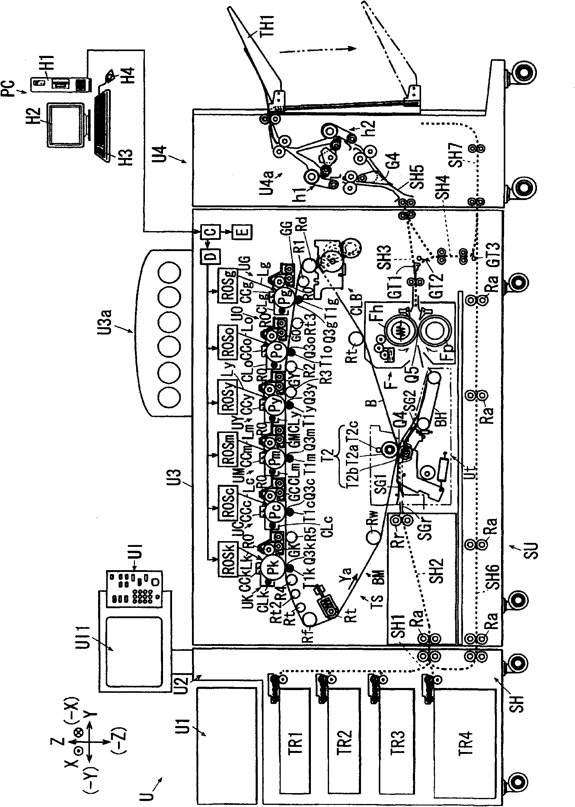
[0036] figure 1 is an explanatory diagram showing the entire image forming apparatus according to Embodiment 1 of the present invention.

[0037] Such as figure 1 As shown, the image forming apparatus U according to Embodiment 1 includes: a user interface UI serving as an example of an apparatus operating portion; an image input device U1 serving as an example of an image information input device; a paper feeding device U2; an image forming device the main body U3; and the sheet handling unit U4.

[0038]The user interface UI is provided with: a copy start key, which is used as an example of an operation start button; a copy quantity setting key, which is used as an example of a key for setting the copy quantity; input buttons such as numeric keys, which are used as numeric input buttons instance of ; and display device UI1.

[0039] The image input device U1 includes an image scanner serving as an example of an image reading device. Such as figure 1 As shown, in the imag...

experiment example 1

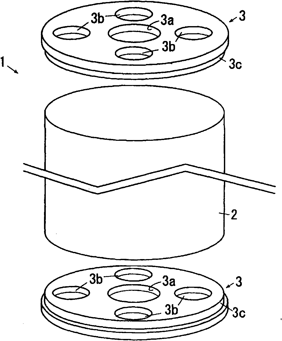
[0120] In Experimental Example 1, a cylindrical body made of SUS 304 stainless steel and having an outer diameter of 600 mm, a thickness of 1.2 mm, and a length of 900 mm was prepared as the cylindrical portion 2 . The cylinder is obtained by crimping and welding a plate having a thickness of 1.2 mm. Sand the seams well to eliminate tendons and steps. The cylindrical portion has a sufficiently small thickness relative to the outer diameter. Thus, the cylindrical portion 2 is deformed by its own weight, and cannot maintain the cylindrical shape without being supported. The surface of the cylindrical portion 2 was roughened by blasting the surface of the cylindrical portion 2 with spherical aluminum particles so that the roughness Ra was 0.4 μm.

[0121] A silicon-based release agent (manufactured by Shin-Etsu Chemical Co., Ltd., trade name: SEPA-COAT (registered trademark)) was applied on the surface of the cylindrical portion 2 by spraying. Then, the cylindrical portion 2 w...


PUM

PropertyMeasurementUnit
thicknessaaaaaaaaaa
thicknessaaaaaaaaaa
lengthaaaaaaaaaa

Abstract

The invention discloses a cylindrical core for manufacturing endless belt-shaped body, and a method for manufacturing endless belt-shaped body. The cylindrical core for manufacturing an endless belt-shaped body includes a cylindrical portion that includes a cylinder whose cylindrical shape is not maintainable without support when an outer surface thereof is orthogonal to the direction of gravitational force; and flange portions that are detachably mounted on both axial ends of the cylindrical portion, wherein the cylindrical core is used in a method for manufacturing an endless belt-shaped body, the method including applying a coating film forming resin solution onto an outer surface or an inner surface of the cylindrical portion in a state in which the flange portions are mounted on the cylindrical portion; drying a solvent of the coating film forming resin solution; and solidifying the coating film forming resin by heating in a state in which the flange portions are removed, to form the endless belt-shaped body.

Description

technical field [0001] The present invention relates to a cylindrical core body for manufacturing an endless belt-shaped body and a method for manufacturing the endless belt-shaped body. Background technique [0002] Hitherto, image forming apparatuses have widely used a resin endless belt-shaped body called an endless belt as an intermediate transfer body and a medium conveyance member, in which a visible image formed on the surface of an image carrier is temporarily Transferred onto the intermediate transfer body, each of the medium conveying members conveys the medium by holding the medium on its surface. Conventionally, techniques described in the following Patent Documents 1 to 3 have been known as methods for producing a seamless endless belt called a seamless belt. [0003] JP-A-2002-91027 ([0022], [0029], [0035] and figure 1 ) describes a technique for producing a seamless belt as follows. That is, a float (5) having a circular hole (6) formed therein floats on th...

Claims


Application Information

Patent Timeline
Patent Type & Authority Applications(China)
IPC IPC(8): G03G15/16C08J5/00
CPCG03G2215/1623G03G15/162
Inventor 矢敷雄一
Owner FUJIFILM BUSINESS INNOVATION CORP
Why Eureka
Try Eureka