Permanent magnet motor

A technology of electric motors and permanent magnets, applied in the field of electric motors, can solve the problems of increased manufacturing errors, deterioration of yield, and dimensional tolerances, and achieve the effects of vibration, suppression of productivity reduction, and reduction of noise.

Active Publication Date: 2010-09-29
HITACHI IND EQUIP SYST CO LTD
View PDF4 Cites 11 Cited by
  • Summary
  • Abstract
  • Description
  • Claims
  • Application Information

AI Technical Summary

Problems solved by technology

At this time, if the length in the direction of the rotation axis is large, the dimensional tolerance and manufacturing error at both ends will increase, and the difference in magnetic properties of each cross-section cannot be ignored.
As a result, during mass production, there is a possibility that the yield may be deteriorated due to individual occurrences due to noise and micro-vibration
That is, even when a plurality of magnets are laminated in the direction of the rotation axis in one slot, there is a problem of h

Method used


Image

  • Permanent magnet motor
  • Permanent magnet motor
  • Permanent magnet motor

Examples


Embodiment Construction

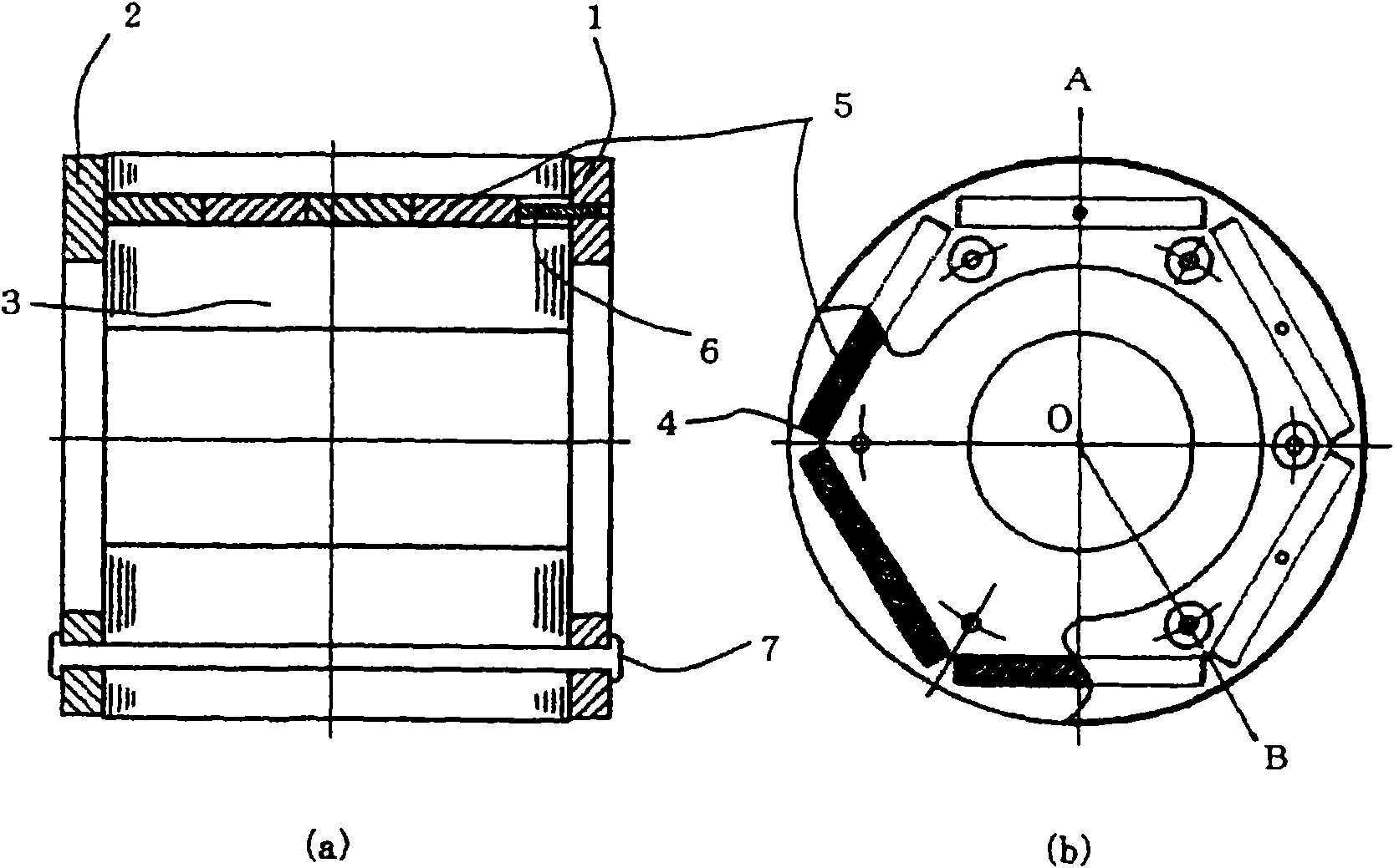
[0031] This embodiment relates to a motor (permanent magnet motor) provided with a permanent magnet inside a rotor, and discloses a configuration that not only improves production efficiency but also takes into account the usage of the motor. The IPM motor is generally configured such that slots are formed in a rotor core composed of laminated iron cores stacked in the direction of the rotation axis, and permanent magnets are arranged in the slots.

[0032] figure 1 It is a figure which shows the rotor of the electric motor of this embodiment. figure 1 (a) is a side sectional view of the rotor, figure 1 (b) is a front view seen from the direction of the rotation axis, and a part is shown in cross-section. figure 1 In (a), the auxiliary line extending left and right indicates the direction of the rotation axis, figure 1 The rotation center O shown in (b) corresponds to the direction of the rotation axis. also, figure 1 (a) is figure 1 (b) Cross-sectional view of line A-B ...


PUM


Abstract

The invention provides a permanent magnet motor capable of preventing the productivity from being reduced and appropriately fixing the permanent magnet simultaneously, and reducing the vibration and noise and achieving high efficiency. The permanent magnet motor comprises a rotor having a laminated iron core (3) in the rotating shaft direction with a plurality of grooves (4) along the rotating direction and a stator for providing the rotating field for the rotor, wherein, the grooves are laminated with a plurality of flat magnets (5) in the length direction, the permanent magnet motor comprises a rotor end plate (1) arranges at one end in the rotating shaft direction of the laminated iron core (3) for covering an opening part at one side of the grooves (4), a rotor end plate (2) arranged at another end at opposite side of the rotor end plate (1) for covering another opening part at the other side of the groove (4), and a press part (6) for pressing the magnet (5) to the rotor end plate (2) from the inner of the projection in the rotating shaft direction of the groove (4) of the rotor end plate (1).

Description

technical field [0001] The present invention relates to electric motors, particularly permanent magnet motors (IPM motors) with built-in magnets. Background technique [0002] Electric motors can be used for various purposes as a driving source, and are often incorporated into various products for internal use. For example, blowers and compressors can also be used in so-called accessories such as power windows and windshield wipers of automobiles. In recent years, from the viewpoint of influence on the global environment, the demand for high efficiency and energy saving has been increasing, and permanent magnet motors have been used in many cases. [0003] Various studies have been conducted on the structure of fixed magnets in permanent magnet motors. For example, Patent Document 1 and Patent Document 2 disclose permanent magnet rotors in which magnets are fixed by end plates provided on both end surfaces of an iron core laminate. In addition, Patent Document 3 discloses...

Claims


Application Information

Patent Timeline
IPC IPC(8): H02K21/12H02K1/27
Inventor 高桥秀一佐藤和雄天池将安部惠辅
Owner HITACHI IND EQUIP SYST CO LTD
Why Eureka
Try Eureka