Method for operating a valve

A technology for operating valves and valve discs, applied in the direction of valve operation/release devices, valve fluid energy absorption devices, valve lifts, etc., can solve problems such as obstruction of free flow, friction loss, etc., and achieve good cleaning effect

Active Publication Date: 2010-09-29
ALFA LAVAL KOLDING
View PDF6 Cites 0 Cited by
  • Summary
  • Abstract
  • Description
  • Claims
  • Application Information

AI Technical Summary

Problems solved by technology

However, the structures used as vortex generators have the disadvantage that they also generate vortices during normal operation of the valve and thus at least partially impede the free flow and generate frictional losses

Method used


Image

  • Method for operating a valve
  • Method for operating a valve
  • Method for operating a valve

Examples


Embodiment Construction

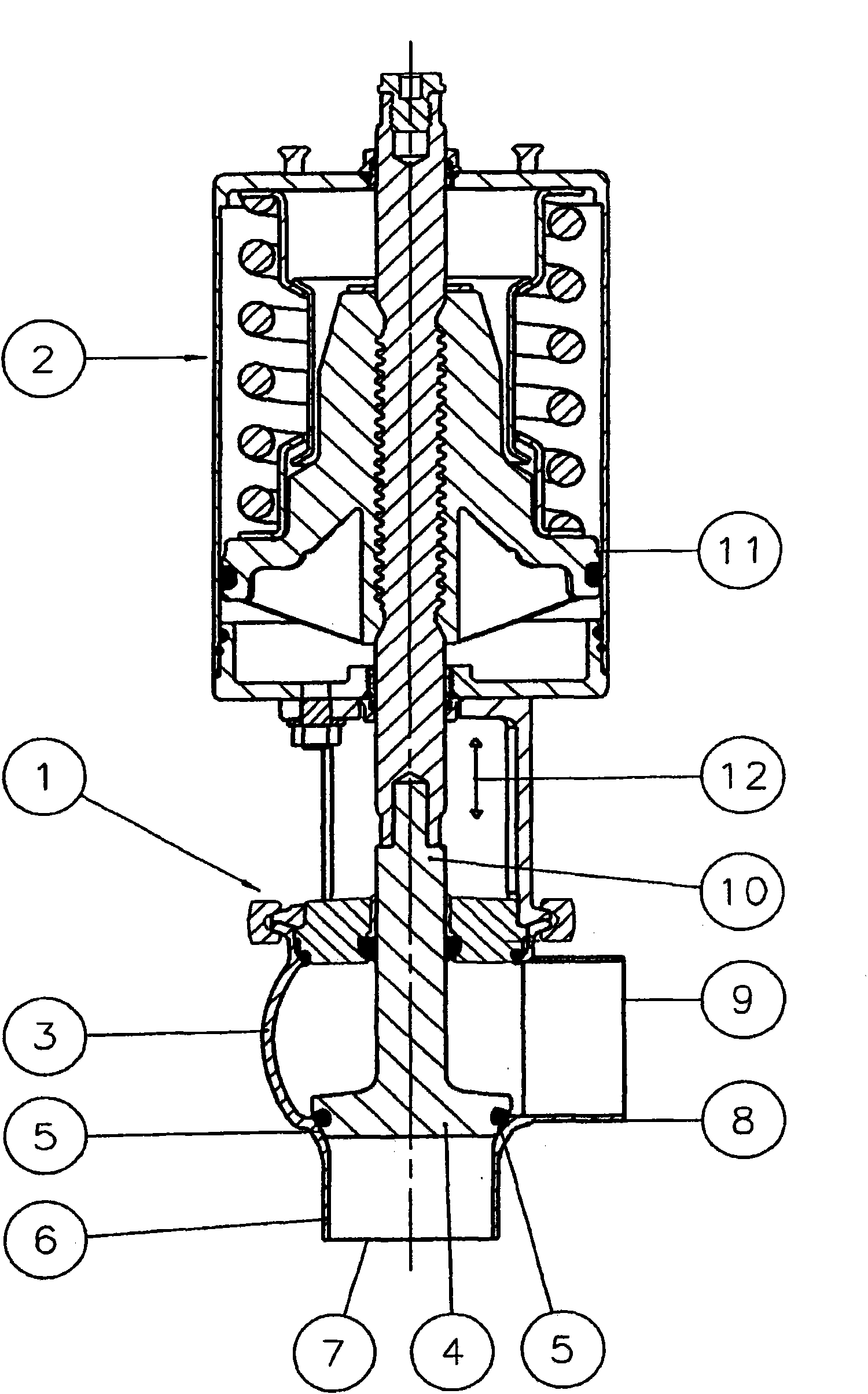
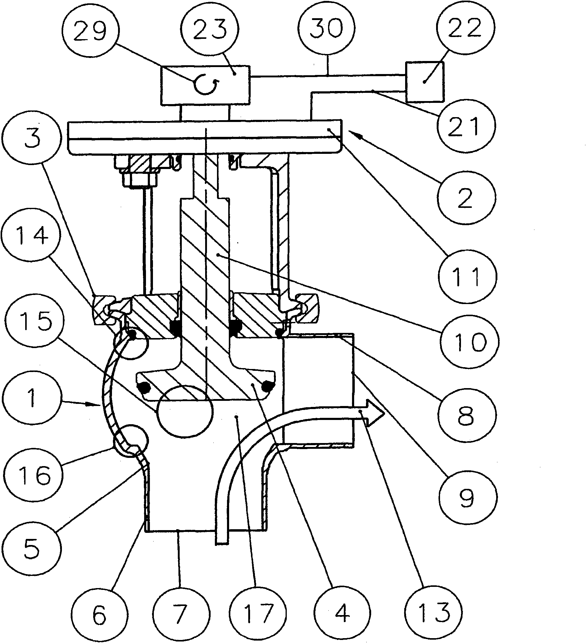
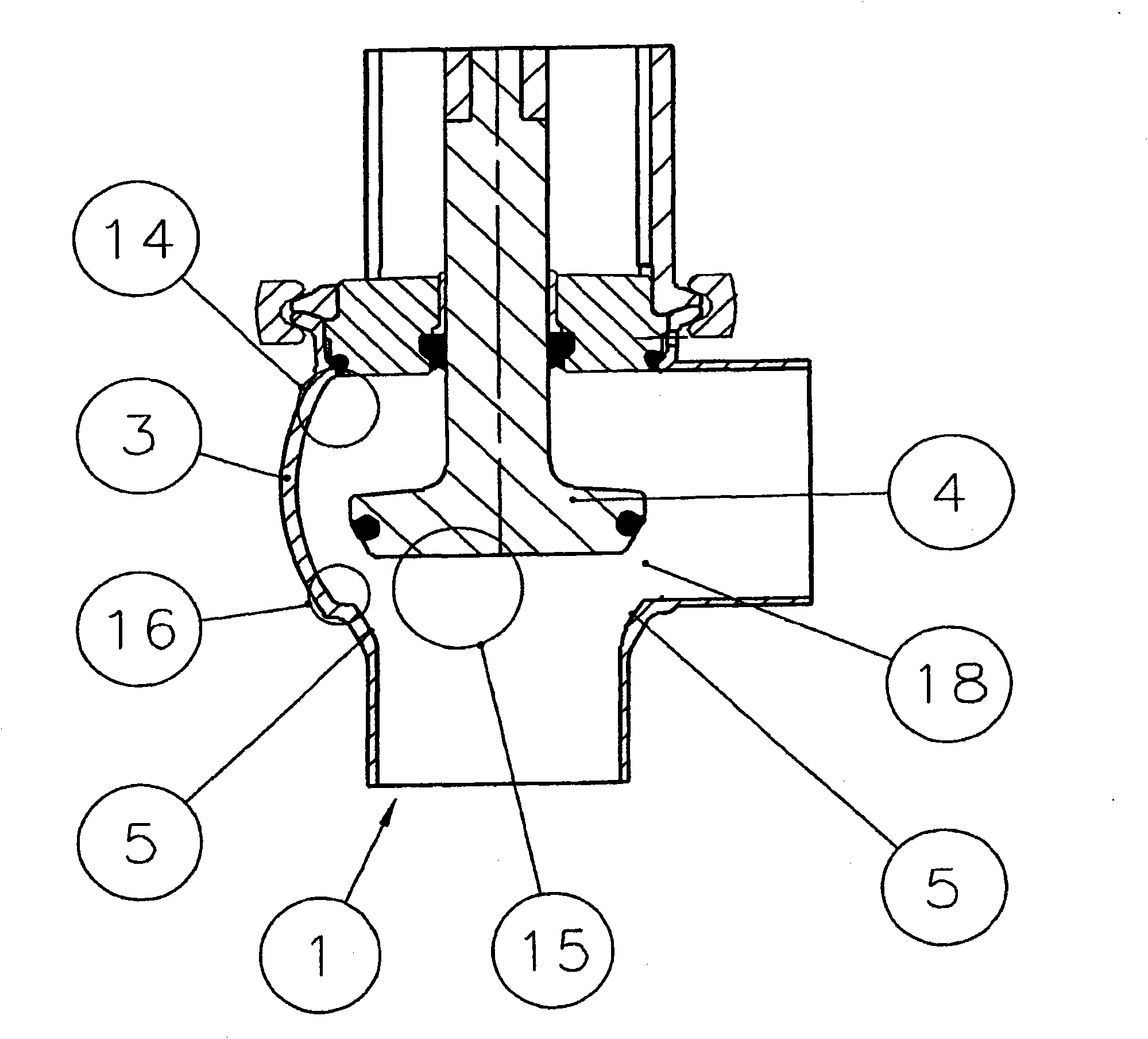
[0054] figure 1 The shown valve arrangement basically comprises a valve 1 and an actuating device 2 . The valve 1 has a valve housing 3 and a valve disc 4; in figure 1 In the closed position shown, the valve disc 4 is pressed against the valve seat 5 . The pipe connection 6 forms an inlet 7 of the valve through which fluid flows into the valve. The pipe connection 8 is arranged at right angles to the pipe connection 6 and serves as an outlet 9 from which the fluid is discharged. exist figure 1 In the closed state of the valve shown, no fluid can pass from the inlet 7 to the outlet 9 .

[0055] The valve disc 4 is connected to an actuating rod 10 which, for its part, is operatively connected to a pneumatic motor 11 of the actuating device 2 . The actuating rod 10 and thus the valve disk 4 can be moved up and down in the direction of the arrow 12 by means of the electric motor 11 . Due to moving down, such as figure 1 As shown, the valve disk 4 is pressed against the valv...


PUM


Abstract

A method for process optimisation for a valve (1) comprising a valve seat (5) arranged in a valve housing (3) between an inlet (7) and an outlet (8), comprising a valve disk (4) which is connected to an actuating rod (10) and comprising an actuating device (2) which acts on the actuating rod (10), by which means the valve disk (4) is brought into a closed position (23) for closing the valve (1) and is pressed onto the valve seat (5) and for opening the valve (1) is raised from the valve seat (5) and brought into an opening position (26), wherein fluid flows through the valve (1) for carrying out the method in the course of cleaning, can be improved with regard to a better cleaning effect in remote regions (14, 15, 16) of the interior (17) of the valve housing (3) whereby during cleaning the valve disk (4) is brought into at least one intermediate position (24, 24, 31) between the closed position (23) and the open position (26).

Description

technical field [0001] The invention relates to a method for process optimization of a valve comprising a valve seat, a valve disc, and Actuating means, the valve seat is arranged in the valve housing between the inlet and the outlet, the valve disc is connected to the actuating rod, the actuating means act on the actuating rod, whereby, in order to close the valve, the valve disc is brought to the closed position and It is pressed onto the valve seat, and in order to open the valve, the valve disc is lifted from the valve seat and brought into the open position. In this case, cleaning fluid flows through the valve for carrying out the method during cleaning. Background technique [0002] A valve arrangement suitable for carrying out the general method is known from WO 2007 / 061519 A1. During cleaning, cleaning fluid flows through the interior of the valve housing via the inlet and outlet. In this case, there are inner regions through which the cleaning fluid flows only in...

Claims


Application Information

Patent Timeline
Patent Type & Authority Applications(China)
IPC IPC(8): F16K47/02F16K51/00
CPCF16K31/046F16K1/54Y10T137/0318Y10T137/043Y10T137/4259
Inventor J·F·安德森K·沙克马德森K·雷霍夫
Owner ALFA LAVAL KOLDING
Why Eureka
Try Eureka