Tyre safety rubber coating mechanism

A tire and safety technology, which is applied to devices and coatings that apply liquid to the surface, can solve the problems of complex mold shapes, high manufacturing costs, laborious and time-consuming construction, etc.

Inactive Publication Date: 2010-10-06
戴建进 +1
View PDF1 Cites 7 Cited by
  • Summary
  • Abstract
  • Description
  • Claims
  • Application Information

AI Technical Summary

Problems solved by technology

However, this mechanism has many shortcomings, such as: the complex shape of the mold leads to high manufacturing costs, and because the inner mold needs

Method used


Image

  • Tyre safety rubber coating mechanism
  • Tyre safety rubber coating mechanism
  • Tyre safety rubber coating mechanism

Examples


Embodiment Construction

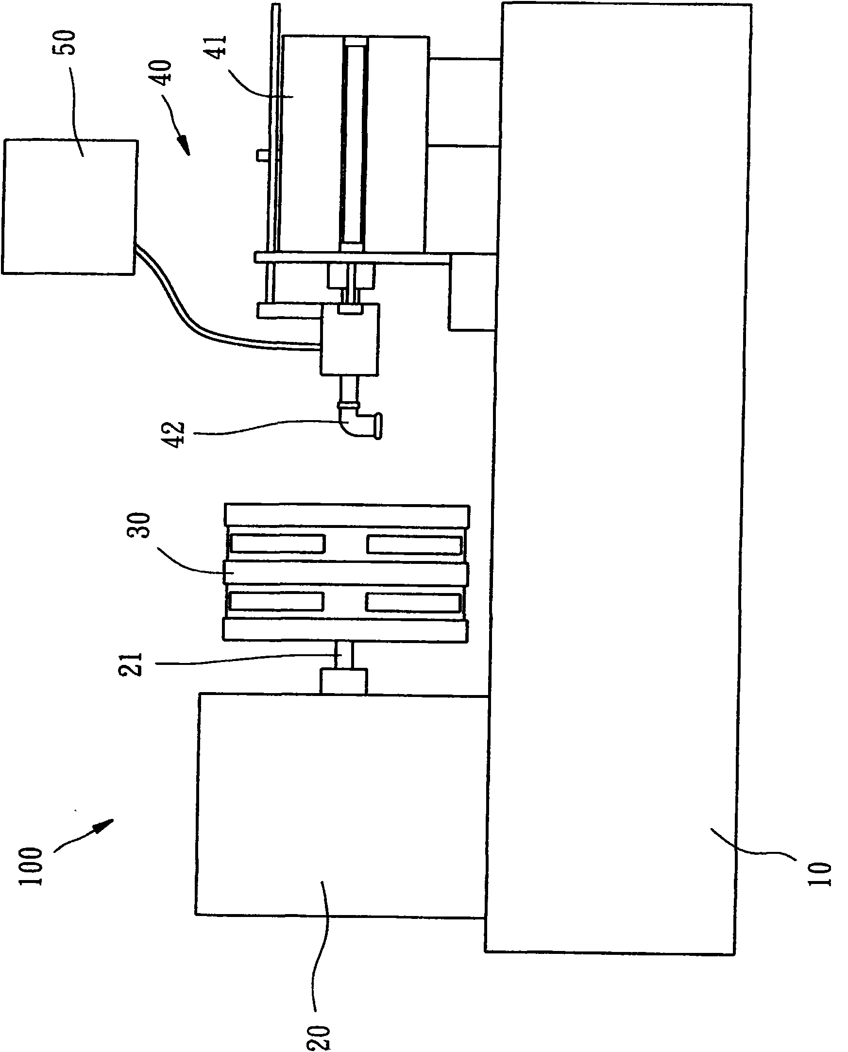
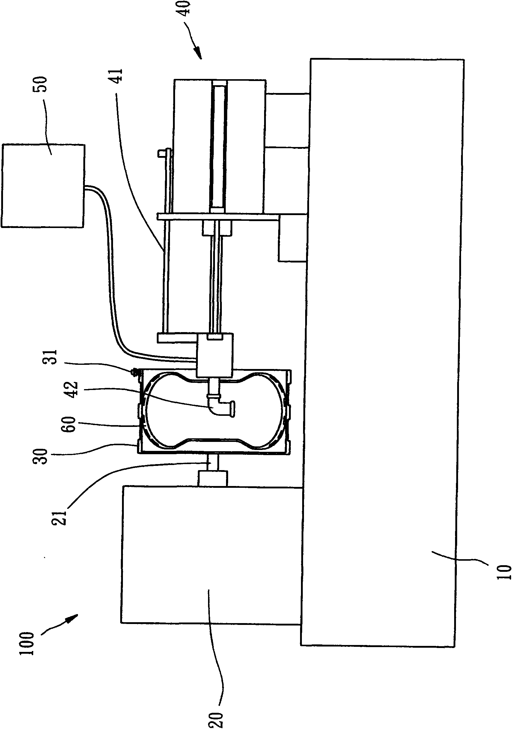
[0014] see figure 1 , is a tire safety rubber coating mechanism 100 provided by a preferred embodiment of the present invention, which mainly includes a machine 10, a rotating device 20, a mold 30, a coating device 40 and a heating storage device 50 ;in:

[0015] The machine platform 10 can be stably placed on a plane.

[0016] The rotating device 20 is a motor assembly fixed on the machine table 10 and has an output shaft 21 that can rotate at a predetermined speed.

[0017] The mold 30 is roughly a circular frame, fixedly connected to the output shaft 21 of the rotating device 20 , and can be driven by the rotating device 20 to rotate coaxially with the output shaft 21 .

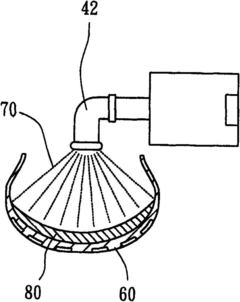
[0018] The coating device 40 has a reciprocating displacement assembly 41 and a spray head 42. The reciprocating displacement assembly 41 is arranged on the machine platform 10 and can be moved from a first position to a second position along the machine platform 10. The spray head 42 is fixed on the re...


PUM


Abstract

The invention discloses a tyre safety rubber coating mechanism, which comprises a machine station, a rotating device, a die, a coating device and a heating storage device, wherein the rotating device is arranged on the machine station to rotate; the die is arranged on the rotating device; a tyre is clamped in the die; the coating device is equipped with a reciprocating displacement component and a sprayer; the reciprocating displacement component is arranged on the machine station; the sprayer is arranged on the reciprocating displacement component; when the reciprocating displacement component is positioned at a first or a second position, the sprayer is located inside or outside of the tyre clamped in the die; and the heating storage device is used for accommodating safety rubber and enabling the safety rubber to be in a liquid state; and the heating storage device is communicated with the sprayer. Therefore, when the rotating device drives the die and the clamped tyre thereof to rotate, and the reciprocating displacement component is located on the secnd position, the liquid safety rubber in the heating storage device can be sprayed and coated on the inner wall of the tyre by the sprayer in a timed and quantitative manner, and the elastic solid safety rubber can be obtained after the liquid safety rubber sprayed and coated on the inner wall of the tyre is cooled.

Description

technical field [0001] The present invention is related to the peripheral equipment of tire manufacturing, and more specifically refers to a mechanism for applying safety glue to the inner wall of the tire. Background technique [0002] According to the traditional pneumatic tires used by general vehicles, when nails or other sharp objects are pierced, the gas filled in the tires will leak from the holes, which will cause the tires to have insufficient tire pressure, so that It is difficult to drive a vehicle. If the driver cannot replace the tire in time or repair the hole and continues to drive, there will be the possibility of accidents. [0003] In view of the shortcomings of the above-mentioned tires, some operators have developed a mechanism (such as China Taiwan Patent Application No. 85104188) that can be applied to the inner wall of the tire to prevent the inner wall of the tire from being pierced by sharp objects When the sharp object is pulled away, the safety co...

Claims


Application Information

Patent Timeline
IPC IPC(8): B05C7/02B05C11/08B05C11/11B05C13/02B05C21/00
Inventor 戴建进戴文彬
Owner 戴建进
Why Eureka
Try Eureka