Hydraulic control pipeline of excavator

A technology for controlling pipelines and excavators, which is applied in the direction of mechanically driven excavators/dredgers, etc., can solve the problems of not being able to connect hydraulic shears with rotary operation, modifying the structure of the spool, and limited interfaces of the spare spool, etc. Achieve the effect of improving multi-functionality, reducing construction cost and reducing investment

Inactive Publication Date: 2012-01-11
SANY HEAVY MACHINERY
View PDF0 Cites 0 Cited by
  • Summary
  • Abstract
  • Description
  • Claims
  • Application Information

AI Technical Summary

Problems solved by technology

However, the current replacement devices are usually construction devices with a single action, such as breaking hammers, grabs, etc., which only need to be connected to the oil circuit of one oil cylinder to complete the operation, and cannot be connected to hydraulic shears with rotary operation. Because the hydraulic shear not only has the cutting function, but also needs to be connected to the rotary motor, so it is necessary to have one more spool to control the oil supply, and the interface on the spare spool is limited, it is difficult to extract two sets of interfaces to provide a very useful replacement device to use
In addition, the spool is an integral structure, which is packaged in the housing, leaving only a few ports to connect with the corresponding pipelines. Therefore, it is impossible to modify the structure of the spool from the inside of the spool to achieve the purpose of increasing the inlet. With the current structure, when it is necessary to use hydraulic shears and other replacement devices controlled by multiple spools, the excavator cannot be connected with its quick change. Therefore, it is still necessary to equip a variety of construction machinery on some construction sites to meet construction needs, thus increasing the construction cost and reducing the construction efficiency

Method used


Image

  • Hydraulic control pipeline of excavator
  • Hydraulic control pipeline of excavator
  • Hydraulic control pipeline of excavator

Examples


Embodiment 1

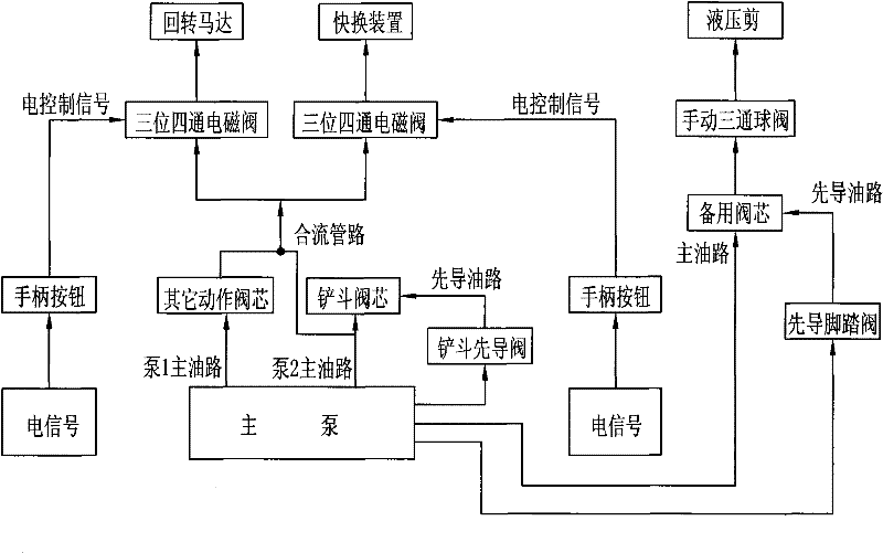
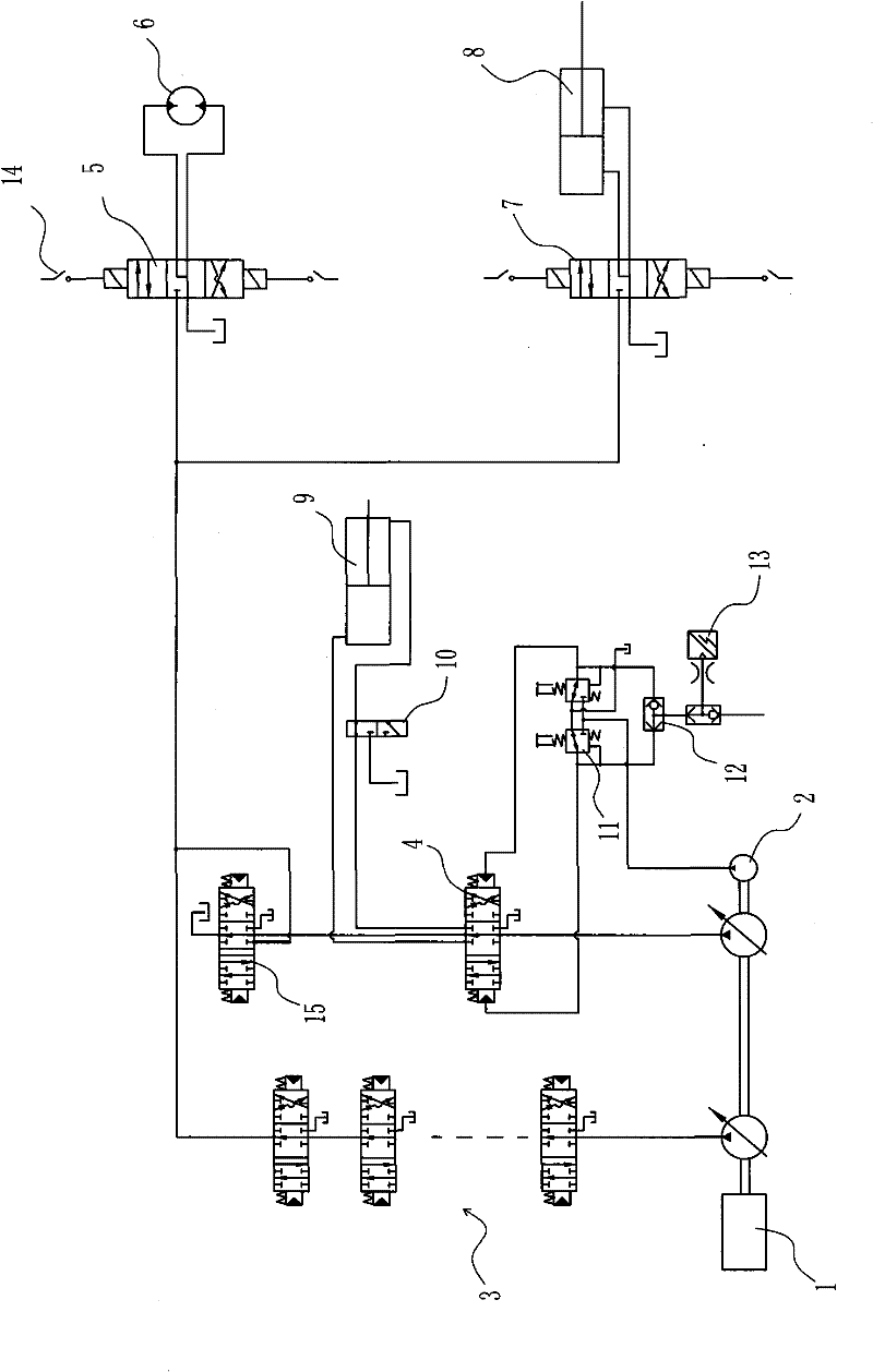
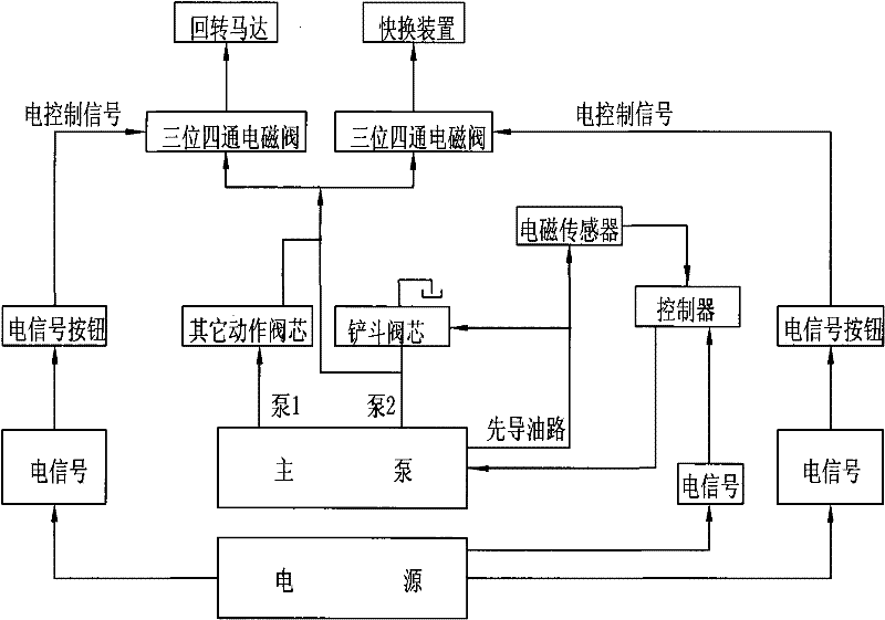
[0020] Embodiment one: see Figure 1~3 As shown, a hydraulic control pipeline of an excavator includes a pump 1, a pump 2, a pilot pump 2 connected to an engine 1, and other action spools 3 connected to the pump 1 and pump 2 (boom spool, bucket Rod spool, bucket spool 15), spare spool 4, connected to the pilot control pipeline between the pilot pump 2 and the pilot port of each valve core, located on the bucket confluence pipeline and connected to the first and second two-way control Pipeline, wherein, the first control pipeline is connected to the hydraulic shear rotary motor 6 through a three-position four-way solenoid valve 5, and the second control pipeline is connected to the quick change device 8 through a three-position four-way solenoid valve 7 connected, the hydraulic shearing cylinder 9 is connected with the spare spool 4, and a manual three-way ball valve 10 is arranged between the rod chamber oil of the hydraulic shearing cylinder 9 and the spare spool 4, and the s...


PUM


Abstract

The invention discloses a hydraulic control pipeline of an excavator, which comprises a pump 1, a pump 2, a pilot pump, a movable arm valve core, a bucket arm valve core, a bucket valve core, a standby valve core and pilot control pipelines, wherein the pump 1, the pump 2 and the pilot pump are connected with an engine; the movable arm valve core, the bucket arm valve core, the bucket valve core and the standby valve core are connected with the pump 1 and the pump 2; and the pilot control pipelines are connected between the pilot pump and valve core pilot ports. The invention is characterizedin that the hydraulic control pipeline of the excavator is arranged on a bucket convergence pipeline and connected with a first control pipeline and a second control pipeline in parallel; the first control pipeline is connected with a rotary motor of a hydraulic cutter through an electromagnetic valve; the second control pipeline is connected with a quick-changing device through the electromagnetic valve; and the hydraulic cutter cylinder is connected with the standby valve core. In the invention, two control paths are added on the bucket convergence pipeline to be respectively connected withthe rotary motor of the hydraulic cutter and the quick-changing device, and the hydraulic cutter cylinder is connected with the standby valve core, thereby realizing quickly changing of the hydrauliccutter and the bucket, fully displaying the utilization ratio of the excavator, enhancing the functions of the excavator and lowering the construction cost.

Description

technical field [0001] The invention relates to a hydraulic control pipeline of an excavator. Background technique [0002] Hydraulic excavators are widely used in foundation excavation of housing construction and cleaning after completion, urban pipeline laying, farmland water conservancy construction, mine excavation, road construction, etc., and have the characteristics of a wide range of applications in earthwork operations. [0003] The hydraulic excavator constructs the site through various actions of the boom, stick, and bucket. Construction, when encountering waste walls or other abandoned buildings to be demolished, especially walls with steel bars, the work tool bucket of the excavator cannot complete the demolition work, and construction machinery equipped with hydraulic shears or other devices is required To operate, thus greatly reducing the use of excavators, the maximum utilization of excavator resources cannot be achieved, and the utilization of excavators i...

Claims


Application Information

Patent Timeline
Patent Type & Authority Patents(China)
IPC IPC(8): E02F3/42E02F3/43
Inventor 戴晴华陈克雷王升东
Owner SANY HEAVY MACHINERY
Why Eureka
Try Eureka