
Flexible screen mounting structure and flexible LED display screen

A technology of LED display screen and installation structure, which is applied in the direction of lighting devices, identification devices, lighting and heating equipment, etc., and can solve the problems of easy damage, storage, inconvenient transportation, movement, transportation, and installation.

Inactive Publication Date: 2010-10-06
理工大高新技术研究院(高邮)有限公司
View PDF10 Cites 23 Cited by
  • Summary
  • Abstract
  • Description
  • Claims
  • Application Information

AI Technical Summary

Problems solved by technology

[0003] In the prior art, the LED display screen generally adopts the form of a box body, which has the functions of protection and load-bearing for the LED display screen, and because all components are fixed in the box body, the box body is very heavy, and, because Each LED unit board is integrated with the box body, which is very bulky when moving, transporting, and installing, which increases the difficulty of moving, transporting, and installing
[0004] Moreover, in the prior art, the LED display screen is also set as a transparent LED display screen, which greatly reduces the weight and volume of the LED display screen. However, due to the fixed volume of the general transparent LED display screen, the volume is still relatively large. The transportation process is still inconvenient; or, in the prior art, various LED units are connected by wires to form a flexible display screen, but because the wires are directly connected and installed, the wires are very easy to be damaged during installation and use, resulting in The reliability of the whole screen is reduced

Method used


Image

  • Flexible screen mounting structure and flexible LED display screen
  • Flexible screen mounting structure and flexible LED display screen
  • Flexible screen mounting structure and flexible LED display screen

Examples


Embodiment 1

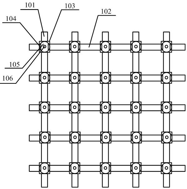
[0024] Such as figure 1 As shown, this embodiment provides a flexible screen body installation structure, the flexible screen body installation structure includes a flexible installation belt and several installation units; the flexible screen body installation structure is used to install each LED unit, and each The LED units form a flexible LED display screen, which is used to display various graphics, characters, letters, video animations, etc.

[0025] The flexible installation belt is a grid-shaped flexible installation belt composed of several horizontal bars 102 and some vertical bars 101 fixedly connected to each other. For example, each horizontal bar 102 and each vertical bar 101 can be fixed to each other by setting a fixing device; The shaped flexible mounting belt has the characteristics of being foldable at will, transparent, good heat dissipation effect, and light in size.

[0026] The flexible installation belt is made of soft material, which can be folded and...

Embodiment 2

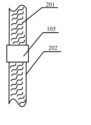
[0035] Such as figure 2 As shown, on the basis of the above examples, in the flexible screen installation structure provided in this embodiment, a number of anti-skid teeth 201 are also provided on the surface of the flexible installation belt 202, wherein each anti-skid tooth 201 can be set as the The tooth-shaped protrusions on the surface of the flexible installation belt, by setting the anti-slip teeth 201, can increase the sliding resistance between each installation unit 105 and the flexible installation belt 202, so that when installing and dismounting each installation unit, it is avoided due to the large sliding range. , so that the positions of each installation unit 105 and the flexible installation belt 202 are difficult to fix, increasing the difficulty of installation and disassembly, especially during installation; and each anti-slip tooth 201 can also make each LED unit and the flexible installation belt The fixing of 202 is more stable.

[0036]And, the shap...

Embodiment 3

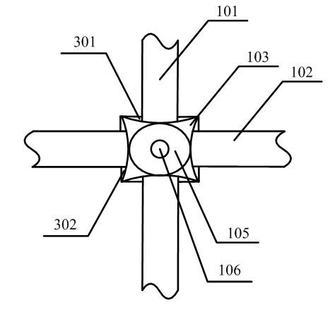
[0038] Such as image 3 As shown, on the basis of the above examples, in the installation structure of the flexible screen provided in this embodiment, the moving positioning sleeve 103 is provided with one or more first sets of holes 302 along the transverse direction and one or more second sets of holes 302 along the longitudinal direction. Two sets of holes 301, wherein, the first set of holes 302 is used for nesting each horizontal bar, and the second set of holes 301 is used for nesting each of the vertical bars; by setting the first set of holes 302 and the second set of holes 301, it is possible to Make each installation unit 105 move laterally along each horizontal bar relative to each vertical bar, thereby changing the lateral spacing of its correspondingly installed LED units, and make each installation unit 105 move longitudinally relative to each horizontal bar along each vertical bar, thereby It is possible to change the longitudinal spacing of the corresponding i...


PUM


Abstract

The invention discloses a flexible screen mounting structure and a flexible LED display screen. The flexible screen mounting structure comprises a flexible mounting belt and a plurality of mounting units, wherein the flexible mounting belt is a grid flexible mounting belt consisting of a plurality of cross strips and vertical strips fixedly connected; the mounting units are arranged in a dot matrix and arranged on intersected positions of the cross strips and vertical strips; each mounting unit is provided with at least one positioning part and at least two fixing parts; the positioning part is used for positioning and fixing the mounting unit on the flexible mounting belt; the mounting units are used for mounting and fixing various LED units correspondingly one to one; each fixing part is used for respectively mounting and fixing an LED unit corresponding to the fixing part; and each mounting unit also comprises a movable positioning sleeve used for making the mounting unit directionally moving along the cross strip or the vertical strip. The invention has the advantages of simple structure, convenient and flexible mounting, convenient transportation, and difficult damage during mounting and using various LED units.

Description

technical field [0001] The invention relates to a lighting device, in particular to a flexible screen body installation structure and a flexible LED display screen. Background technique [0002] LED has been widely valued for its high luminous efficiency, long service life, safety, reliability, environmental protection and energy saving. As an important means of information dissemination, LED display has become a symbol of urban information modernization. With the continuous progress of social economy and the continuous improvement of LED display technology, people's understanding of LED display will become more and more in-depth. , and its application fields will become wider and wider. [0003] In the prior art, the LED display screen generally adopts the form of a box body, which has the functions of protection and load-bearing for the LED display screen, and because all components are fixed in the box body, the box body is very heavy, and, because Each LED unit board i...

Claims


Application Information

Patent Timeline
IPC IPC(8): G09F9/33F21V19/00
Inventor 商松
Owner 理工大高新技术研究院(高邮)有限公司
Learn More