
Magnetic element with permanent magnetic bias

A magnetic component and permanent magnet technology, applied in the field of magnetic components, can solve the problems of permanent magnet temperature failure, permanent magnet demagnetization, eddy current loss, etc., and achieve the effects of improving anti-bias ability, reducing cross-sectional area, and increasing inductance

Inactive Publication Date: 2010-10-06
FUZHOU UNIV
View PDF5 Cites 2 Cited by
  • Summary
  • Abstract
  • Description
  • Claims
  • Application Information

AI Technical Summary

Problems solved by technology

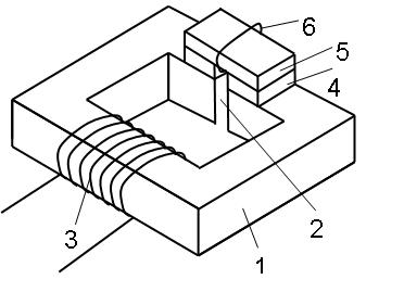
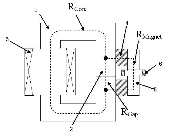
The technical feature of the present invention is that the sintered rare-earth permanent magnet material with a small resistivity but a large bias capability can be used to improve the DC bias performance, and at the same time, through the design of the magnetic circuit reluctance structural parameters and the use of permanent magnets surrounded by magnetic circuits The short-circuit coil overcomes the problems that the sintered rare-earth material permanent magnet itself has a small resistivity due to the large eddy current loss caused by the high-frequency magnetic flux, which leads to the failure of the permanent magnet due to excessive temperature and the permanent magnet is easily demagnetized by the current pulse.

Method used


Image

  • Magnetic element with permanent magnetic bias
  • Magnetic element with permanent magnetic bias
  • Magnetic element with permanent magnetic bias

Examples


specific Embodiment

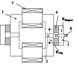
[0020] The invention takes the inductor coil element as an example, but is not limited thereto. It can also be applied to the structure of combined magnetic components that need to use permanent magnetic materials to improve the anti-biasing ability of the magnetic core of the magnetic circuit, such as transformers, multi-channel output integrated inductors and the like. Specific examples are as follows:

[0021] Figure 6 It is composed of a magnetic core 1, a coil 3, two air-gap fractures 2 of two high-side columns, four permanent magnets 4, a soft magnetic material 5, and a short-circuit coil 6 with at least one turn. The thin arrows (polarization direction and bias direction of the permanent magnet) appear opposite to the thick arrows (the direction of the magnetic field generated by the DC coil), and can be reversed at the same time. Due to the biasing effect of the permanent magnet, the direct current power passed through the working coil can be greatly increased. The...


PUM


Abstract

The invention relates to a magnetic element with permanent magnetic bias, comprising a magnetic core which is used for forming a magnetic flux loop and comprises at least one air gap, and the magnetic element is characterized in that a working coil is wound on the magnetic core, a pair of permanent magnets are arranged on at least one side surface of a fracture of the air gap of the magnetic core, at least one soft magnetic core is arranged on the permanent magnets for communicating the two permanent magnets, thereby forming a magnetic branch which is connected with the fracture of the air gap in parallel and contains the permanent magnets; and the magnetic resistance of the fracture of the air gap of the magnetic element is less than 5 times of the magnetic resistance of the magnetic branch which is connected with the fracture of the air gap in parallel and contains the permanent magnets. The magnetic element can effectively improve the anti-direct current magnetic bias capacity of the magnetic core of the magnetic element, improve the inductance value under a certain direct current bias current, or reduce the sectional area of the magnetic core, reduce the volume or reduce the copper consumption, the length and the resistance of the working coil; and the magnetic element can simultaneously overcome the shortcomings that the traditional magnetic element with the permanent magnets is easy to be demagnetized by current pulse, and the eddy current loss of the permanent magnets causes the increase in temperature under high-frequency magnetic flux, so that the permanent magnets are easy to fail at high temperature.

Description

technical field [0001] The invention relates to a magnetic element with permanent magnetic bias, which is suitable for the situation where there is a relatively large DC (or low frequency) magnetic flux on the magnetic core of the magnetic element, and a relatively high frequency AC magnetic flux is superimposed. Background technique [0002] Magnetic components, especially power inductors, are widely used in various power converters, such as Boost inductors in PFC circuits, output filter inductors in DC / DC converters, output inductors in UPS, frequency converters and inverters, etc. However, with the increase of power and the increase of bias magnetic flux density, the core will be saturated, thereby reducing the inductance. In order to solve this problem and further improve the anti-magnetic saturation ability of power inductors, permanent magnet materials are applied to power inductors to use the biasing ability of permanent magnet materials to offset the bias caused by t...

Claims


Application Information

Patent Timeline
Patent Type & Authority Applications(China)
IPC IPC(8): H01F3/00H01F3/14H01F7/02H01F41/02
Inventor 陈为杨海军卢增艺
Owner FUZHOU UNIV
Learn More