Eureka AIR delivers breakthrough ideas for toughest innovation challenges, trusted by R&D personnel around the world.

Method and device for marking a surface using controlled periodic nanostructures

A technology of marking and equipment, applied in the field of nanostructure marking surface, which can solve the problems of slow speed and not allowed to write

Active Publication Date: 2010-10-06
ADVANCED TRACK & TRACE SA
View PDF2 Cites 9 Cited by
  • Summary
  • Abstract
  • Description
  • Claims
  • Application Information

AI Technical Summary

Problems solved by technology

Due to these two characteristics, this marking method is very slow and does not allow writing information other than the symbols traced by the lines to be written

Method used


Image

  • Method and device for marking a surface using controlled periodic nanostructures
  • Method and device for marking a surface using controlled periodic nanostructures
  • Method and device for marking a surface using controlled periodic nanostructures

Examples


Embodiment Construction

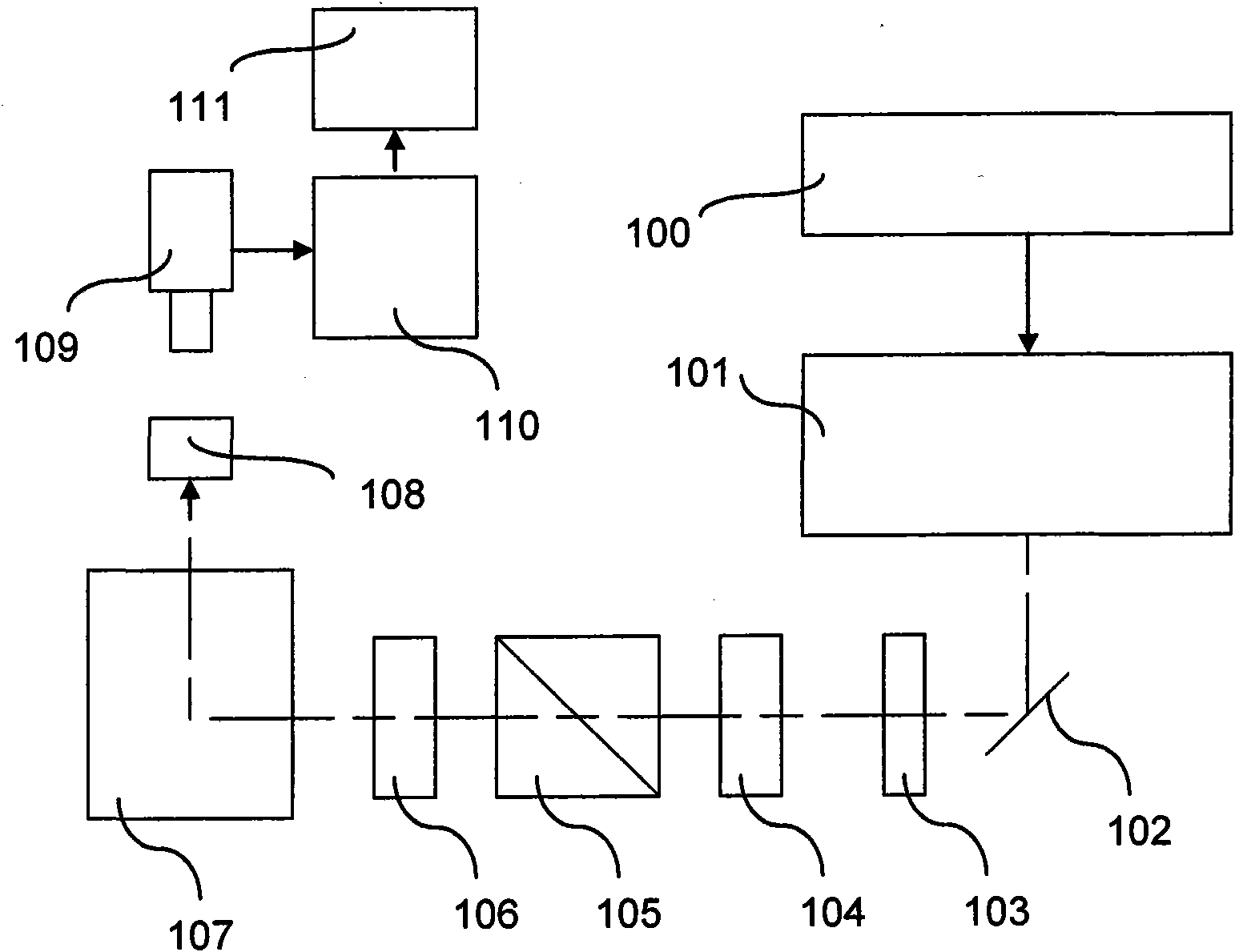
[0049] figure 1 Shown are a control device 100 , a laser 101 , a mirror 102 , an aperture 103 , a polarizer 104 , a separator cube 105 , a polarizer 106 , a scanner 107 and a surface 108 to be marked.

[0050] The control device 100 of the laser 101 is designed to be able to determine the image to be marked on the surface 108, an area table of coded items carrying information for each area forming the image.

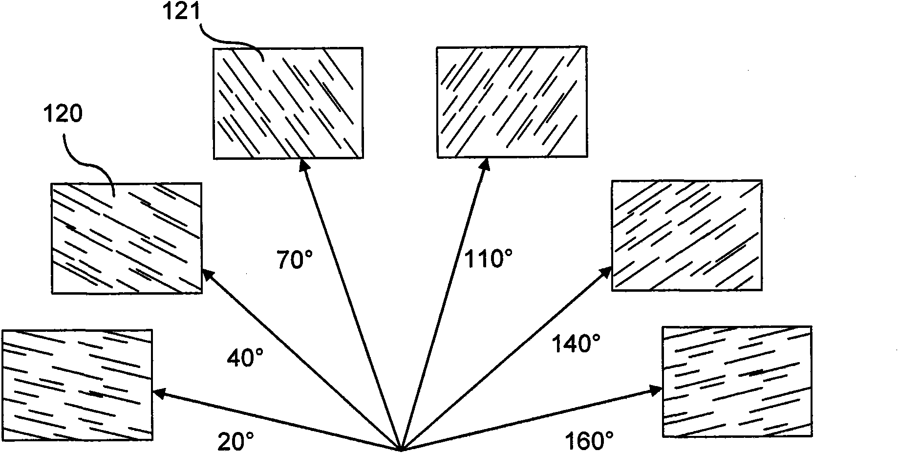
[0051] The information items carried by each field may or may not be binary. As described below, a region carries at least one information value (here each) corresponding to a particular polarization orientation and another information value corresponding to no label, no polarization or a different polarization orientation.

[0052] In an embodiment, the control device 100 receives encoded items of information from a computer system. In another embodiment, the control device 100 receives information to be encoded of an image and calculates the image after encoding the in...


PUM


Abstract

The invention relates to a method for marking a surface with controlled periodic nanostructures, that comprises: a step (500) of encoding information in the form of an image including values representative of the encoded information, and a step (506-514) of point-by-point marking an area of said surface with a polarised laser beam in order to form oriented nanostructures on or in said surface by modulating the polarisation of the laser beam for each marking point based on the value of a point of said image. In some embodiments, during the marking step, the method comprises using a pulsed laser with durations lower than 10x10-12 second and a polarisation means of the light emitted from said laser source and reaching said surface, adapted for polarising the light along a variable polarisation axis based on a signal received by said polarisation means.

Description

technical field [0001] The present invention relates to a method and a device for marking a surface by controllable periodic nanostructures and a method and device for reading information on such a surface. Considering its recognizability, traceability and authenticability, it is especially suitable for marking objects and documents. Background technique [0002] Numerous marking methods are known, for example by printing or modifying the surface state. These marking methods are well suited for continuous marking but offer low security for identifying and authenticating marked objects and documents. In particular, they are often easily copied by counterfeiters. [0003] Furthermore, prior art markings are often visible, which is easily detected, analyzed and destroyed by counterfeiters. [0004] Existing periodic structures with a period of hundreds of nanometers have received scientific attention (see, for example, the Appl. Surf. Sc. 253, 8075-879-2007 accepted, Messrs....

Claims


Application Information

Patent Timeline
Patent Type & Authority Applications(China)
IPC IPC(8): B41M3/14B41M5/24B41M5/26B82B3/00G06K7/12G06K19/06B23K26/06
CPCG06K5/02G06K1/12
Inventor 埃里克·奥多亚德艾伦·福科让皮埃尔·麦斯考特兹比格纽·赛甘本杰明·达瑟米歇尔·茱琳赫唯·索德
Owner ADVANCED TRACK & TRACE SA
Why Eureka
Eureka Blog
Learn More