
Surface nanostructure forming method and base having surface nanostructure

a technology of surface nanostructure and forming method, which is applied in the direction of manufacturing tools, transportation and packaging, layered products, etc., can solve the problems of difficult control of processing form, increase in number of processes, and difficulty in formation of even structures having an extremely high aspect ratio, etc., and achieve high aspect ratio

Inactive Publication Date: 2012-11-22
THE FUJIKURA CABLE WORKS LTD +2
View PDF1 Cites 7 Cited by
  • Summary
  • Abstract
  • Description
  • Claims
  • Application Information

AI Technical Summary

Benefits of technology

[0024]In the second process, by using an anisotropic dry etching method as the etching treatment and by changing a process pressure at the time of etching, the form of the valleys may be controlled.
[0028]In addition, by changing a parameter at the time of etching or the polarization of the laser light, the processing form can be controlled.
[0029]According to the aspects of the invention, it is possible to provide a surface nanostructure forming method in which the processing is simplified, the processing form can be controlled, and an uneven structure which includes valleys having a high aspect ratio can be formed.
[0031]Since the valley is formed by the surface nanostructure forming method of the invention, it has a high aspect ratio.
[0032]As a result, according to the aspects of the invention, it is possible to provide a base which has a surface nanostructure formed of periodic nanostructures having a high aspect ratio.

Problems solved by technology

(1) An uneven structure having an extremely high aspect ratio is not easily formed.
(2) Since a polishing process is required to expose a periodic nanostructures after irradiating the inside of a material with laser light, the number of processes increases.
(3) The periodic nanostructures having a relatively high aspect ratio is easily formed. However, since the etching treatment is carried out with a hydrofluoric acid having a concentration of 1% or less, the processing form is not easily controlled by changing the concentration of the hydrofluoric acid.

Method used


Image

  • Surface nanostructure forming method and base having surface nanostructure
  • Surface nanostructure forming method and base having surface nanostructure
  • Surface nanostructure forming method and base having surface nanostructure

Examples


Embodiment Construction

[0043]Hereinafter, a surface nanostructure forming method and a base according to an embodiment of the invention will be described.

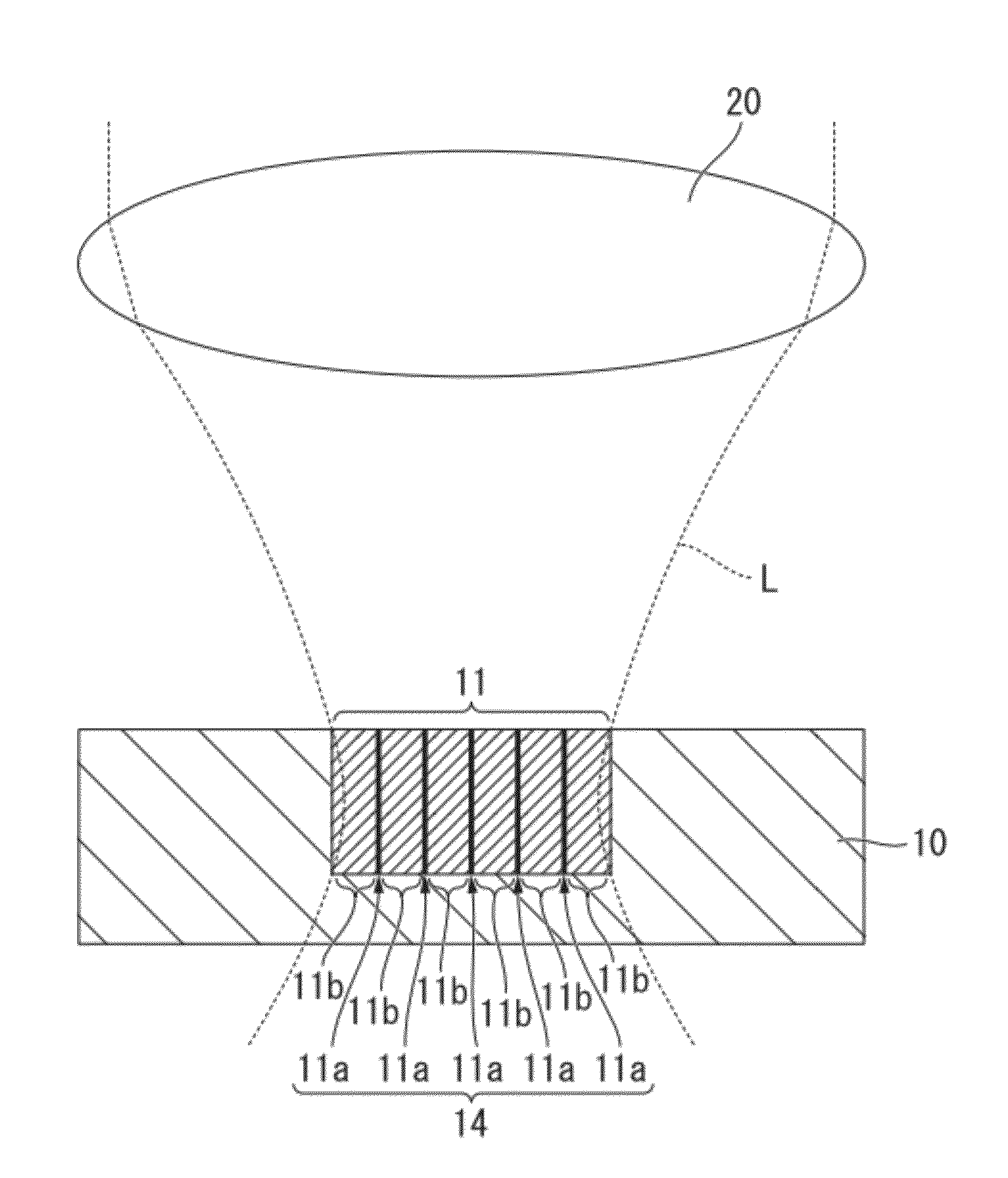
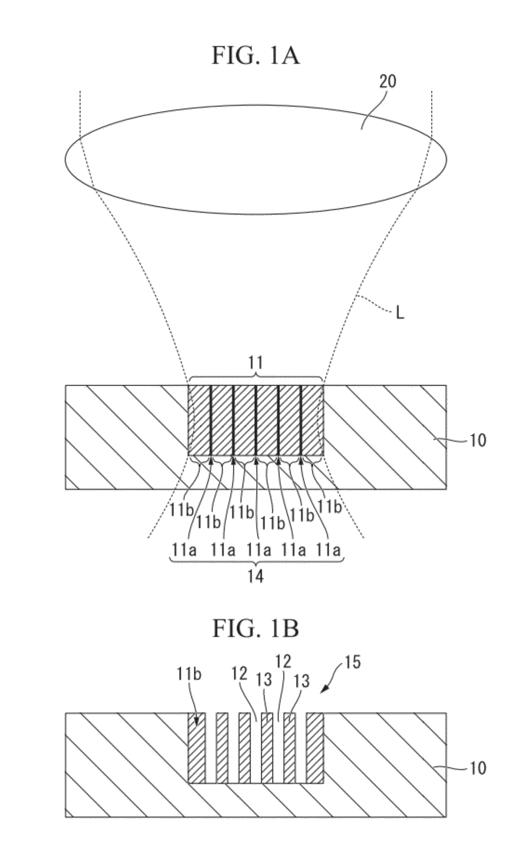
[0044]FIGS. 1A and 1B are cross-sectional views schematically showing a surface nanostructure forming method of this embodiment.

[0045]The surface nanostructure forming method of the invention includes a first process [see FIG. 1A] of irradiating a part which is close to the surface of a substrate 10 with laser light L at an irradiation intensity which is close to, or greater than or equal to an appropriate processing value of the substrate 10 to form periodic nanostructures 14 which is periodically arranged and forms valleys 12 by the next etching treatment in a self-assembled manner in a region which is close to the focus at which the laser light L is concentrated; and a second process [see FIG. 1B] of performing the etching treatment on the surface of the substrate 10 having the periodic nanostructures 14 formed thereon to erode a region forming the va...


PUM

PropertyMeasurementUnit
Threshold limitaaaaaaaaaa

Abstract

A surface nanostructure forming method includes: preparing a substrate having an appropriate processing value; a first process of irradiating a part which is close to a surface of the substrate with laser light having a pulse duration of picosecond order or shorter at an irradiation intensity being close to the appropriate processing value of the substrate, or greater than or equal to the appropriate processing value and less than or equal to an ablation threshold and forming periodic nanostructures in which first modified portions and second modified portions are periodically arranged in a self-assembled manner at a focus at which the laser light is concentrated and in a region being close to the focus; and a second process of performing an etching treatment on the surface of the substrate having the periodic nanostructures formed thereon to form an uneven structure having the first modified portions as valleys.

Description

CROSS REFERENCE TO RELATED APPLICATIONS[0001]This application is a continuation application based on a PCT Patent Application No. PCT / JP2011 / 051900, filed Jan. 31, 2011, whose priority is claimed on Japanese Patent Application No. 2010-024776, filed Feb. 5, 2010, the entire content of which are hereby incorporated by reference.BACKGROUND OF THE INVENTION[0002]1. Field of the Invention[0003]The present invention relates to a surface nanostructure forming method using a laser irradiation and etching, and a base having a surface nanostructure.[0004]2. Description of the Related Art[0005]It is known that when concentrating and applying a laser pulse having a pulse duration of picosecond order or shorter to the inside of a processing material, a modified portion and several nano-order periodic nanostructures perpendicular to the laser polarization are formed on the light-concentrated portion due to the incident light and the plasmon generated due to the laser pulse. In this case, the per...

Claims


Application Information

Patent Timeline
IPC IPC(8): B29C59/16B32B3/30B23K26/00B23K26/36B82Y30/00B82Y40/00
CPCB23K26/0635Y10T428/24479C03C23/0025B23K26/365B23K26/0624B23K26/361B23K26/362
Inventor NUKAGA, OSAMUYAMAMOTO, SATOSHISAMUKAWA, SEIJISUGIYAMA, MASAKAZU
Owner THE FUJIKURA CABLE WORKS LTD
Learn More