Sputtering apparatus and sputtering film forming method

A sputtering and target technology, applied in the field of sputtering film formation, can solve problems such as low heat resistance, and achieve the effect of inhibiting the injection of hot electrons

Inactive Publication Date: 2010-10-06
EBARA-UDYLITE CO LTD
View PDF1 Cites 5 Cited by
  • Summary
  • Abstract
  • Description
  • Claims
  • Application Information

AI Technical Summary

Problems solved by technology

[0008] The present invention was made in order to solve the above-mentioned problems, and its object is to provide a sputtering device that can suppress thermal electrons from entering th...

Method used


Image

  • Sputtering apparatus and sputtering film forming method
  • Sputtering apparatus and sputtering film forming method
  • Sputtering apparatus and sputtering film forming method

Examples


Embodiment Construction

[0023] Below, in conjunction with accompanying drawing, continue to describe the present invention, wherein, accompanying drawing shows the magnetron sputtering device (hereinafter referred to as coaxial type magnetron sputtering device) that uses cylindrical target material as a kind of embodiment of the present invention ).

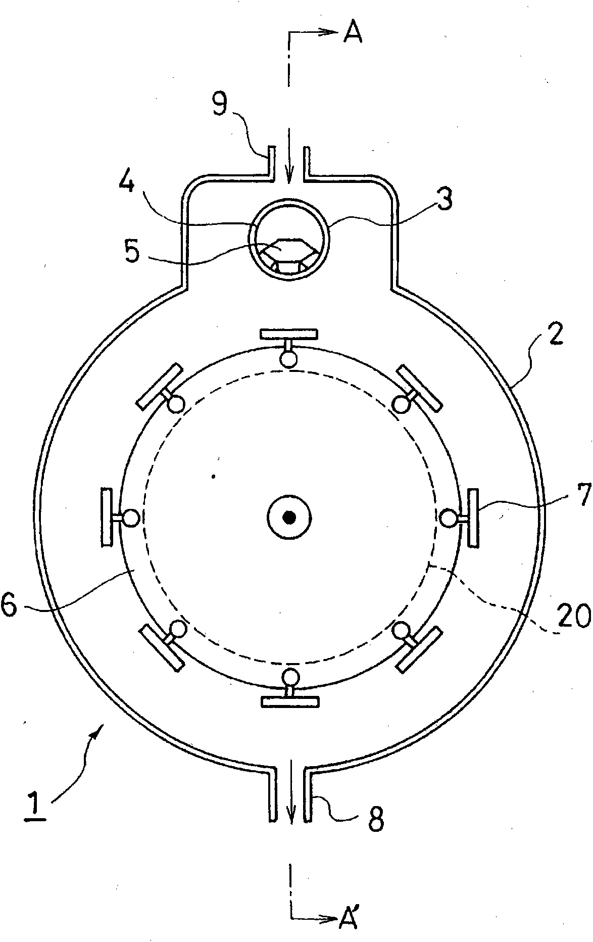
[0024] figure 1 It is a schematic diagram which schematically shows the main part of the coaxial type magnetron sputtering apparatus. In the figure, 1 denotes a coaxial magnetron sputtering device, 2 denotes a vacuum chamber, 3 denotes a cylindrical target, 4 denotes a magnet accommodating part, 5 denotes a target magnet, 6 denotes a turntable workpiece fixture, and 7 denotes a In the workpiece, 8 denotes an exhaust port, 9 denotes a gas inlet, and 20 denotes a thermal electron capture member.

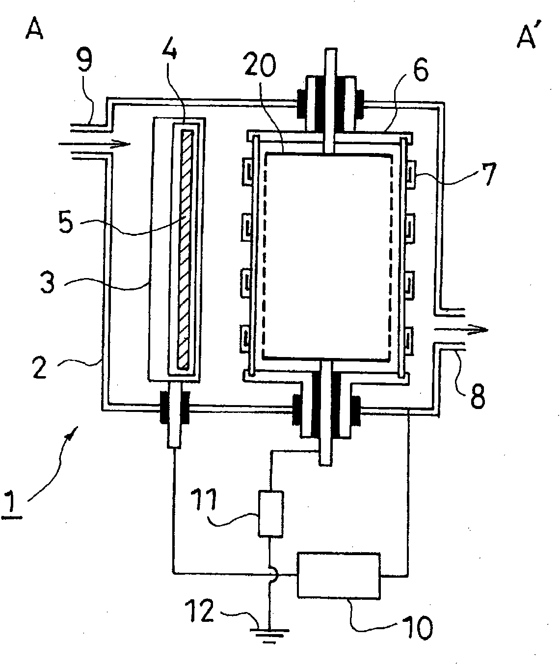
[0025] and, figure 2 for figure 1 A-A' sectional view of . In the figure, the components denoted by numerals 1 to 9 and 20 are the same as those described...


PUM


Abstract

Provided is a sputtering apparatus which suppresses entry of thermal electrons into a work and does not cause problems such as work deformation due to heat, even at the time of forming a film on materials, such as plastic, having a low heat resistance. The apparatus is provided with a target and a carousel-type work holder arranged to face the target with a rotating shaft, in a vacuum chamber. The carousel-type work holder has a work holder supporting section and a plurality of work holding sections. The work holding section is arranged at the outer circumfernce of the work holder supporting section. The carousel-type work holder and/or the work holding section is rotatably arranged by a shaft arranged within a surface vertical to a surface connecting the target and the rotating shaft of the carousel-type work holder. Inside the carousel-type work holder, a thermal electron capturing member is arranged.

Description

technical field [0001] The present invention relates to a sputtering device, and more particularly, to a sputtering device and a sputtering film-forming method capable of suppressing the thermal electrons generated during sputtering from being injected into a workpiece (object to be sputtered). Background technique [0002] The currently known sputtering is a manufacturing technique that requires high-quality thin films such as semiconductors, liquid crystals, plasma displays, and optical discs to form films on metals, plastics, and other workpieces. [0003] However, the thermal electrons generated in the above-mentioned sputtering become the main cause of the temperature rise of the workpiece as the sputtering target (Non-Patent Document 1), and especially when the workpiece is made of a material with low heat resistance such as plastic, Plating causes problems such as workpiece deformation. [0004] Conventionally, it is known that in order to suppress the injection of t...

Claims


Application Information

Patent Timeline
IPC IPC(8): C23C14/34
CPCH01J37/3405C23C14/35C23C14/505C23C14/541H01J37/32761
Inventor 堀江邦明高桥直树
Owner EBARA-UDYLITE CO LTD
Why Eureka
Try Eureka