Box type folding bicycle
A folding bicycle and box-type technology, which is applied to foldable bicycles, bicycles, motor vehicles, etc., can solve the problems of uneven stacking, unsightly appearance, and inconvenient storage, etc., and achieves easy folding and storage. Small and easy to carry
- Summary
- Abstract
- Description
- Claims
- Application Information
AI Technical Summary
Problems solved by technology
Method used
Image
Examples
Embodiment 1
[0118] Example 1. Description of the main structure of the present invention.
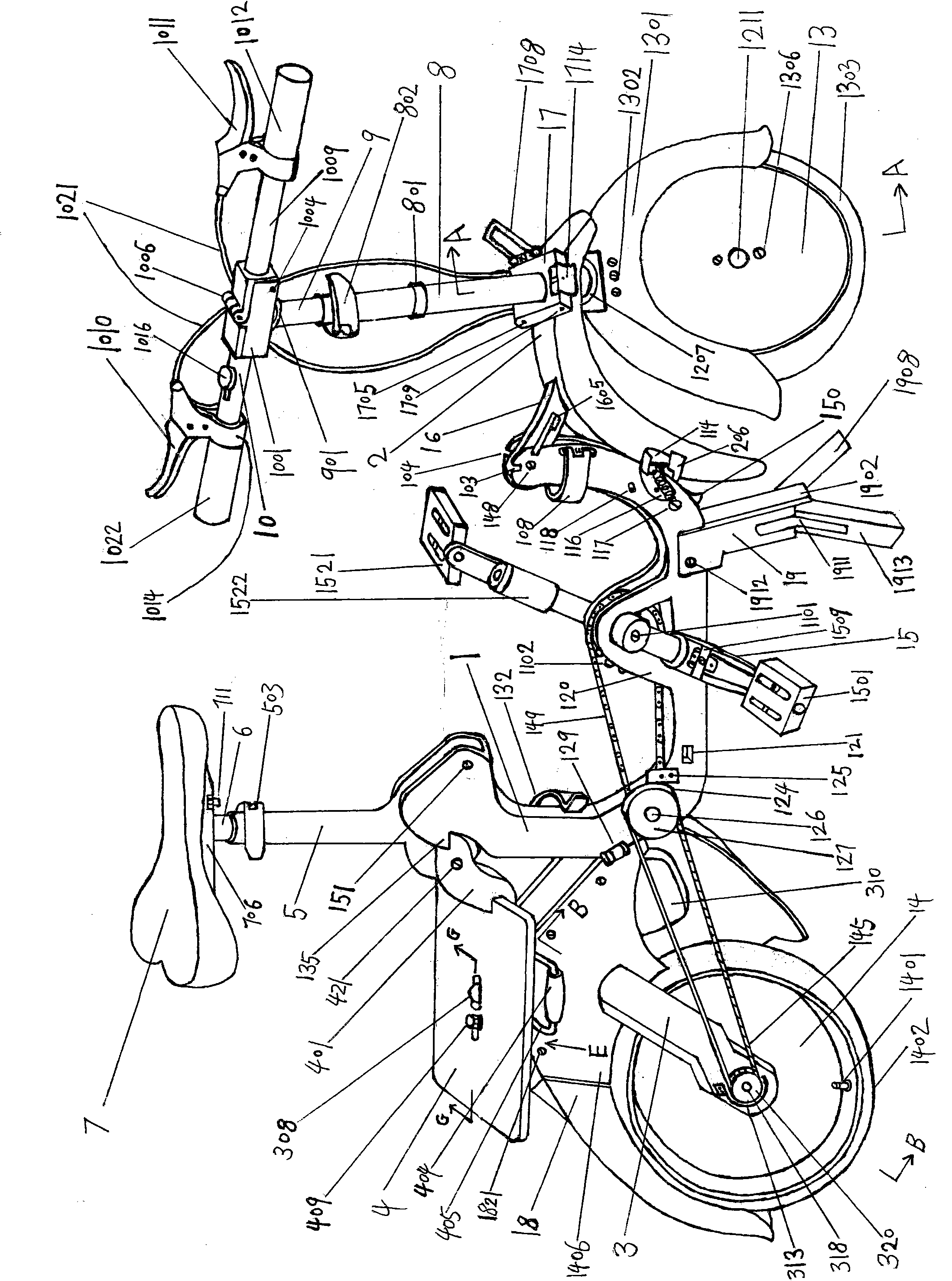
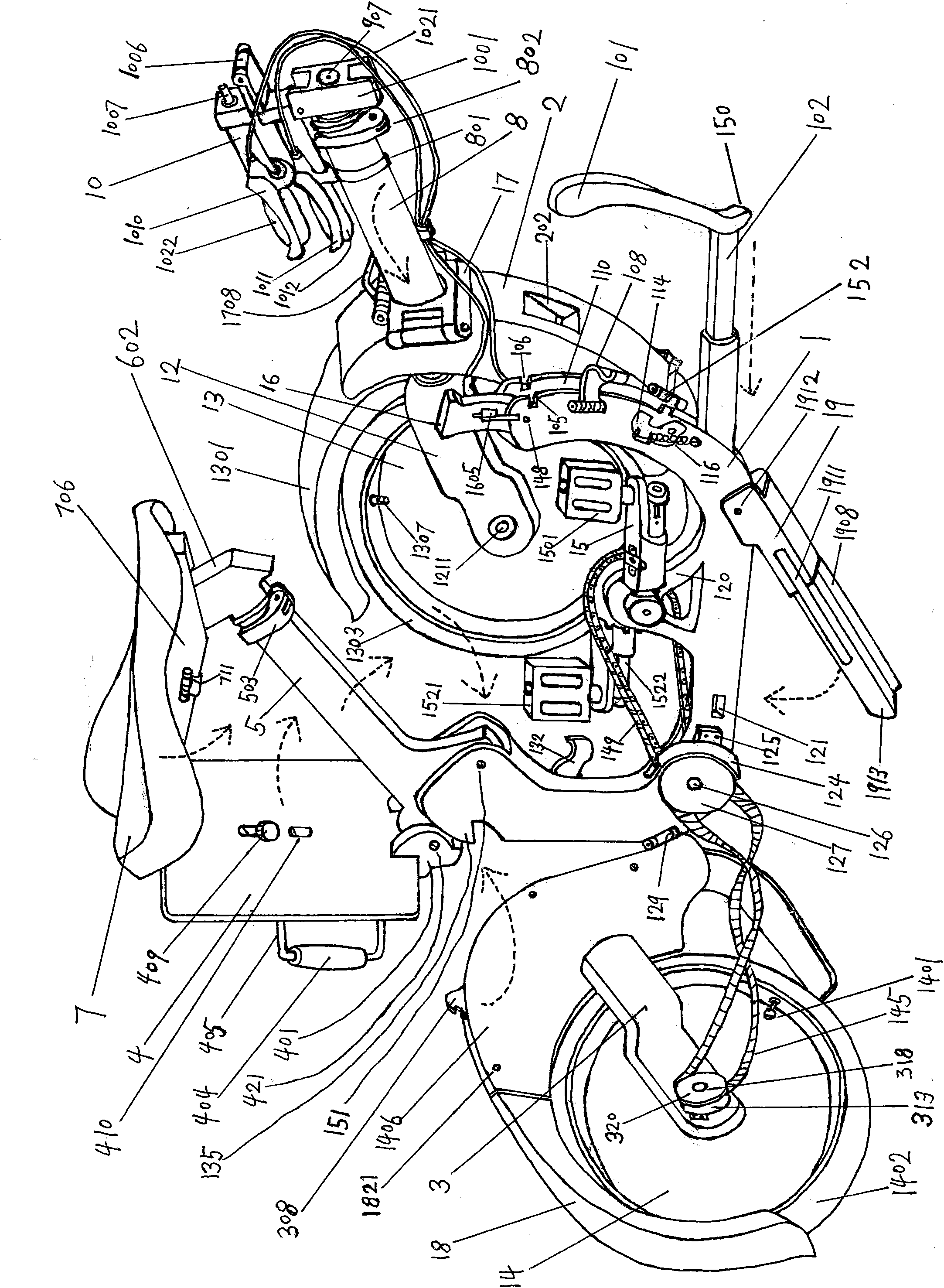
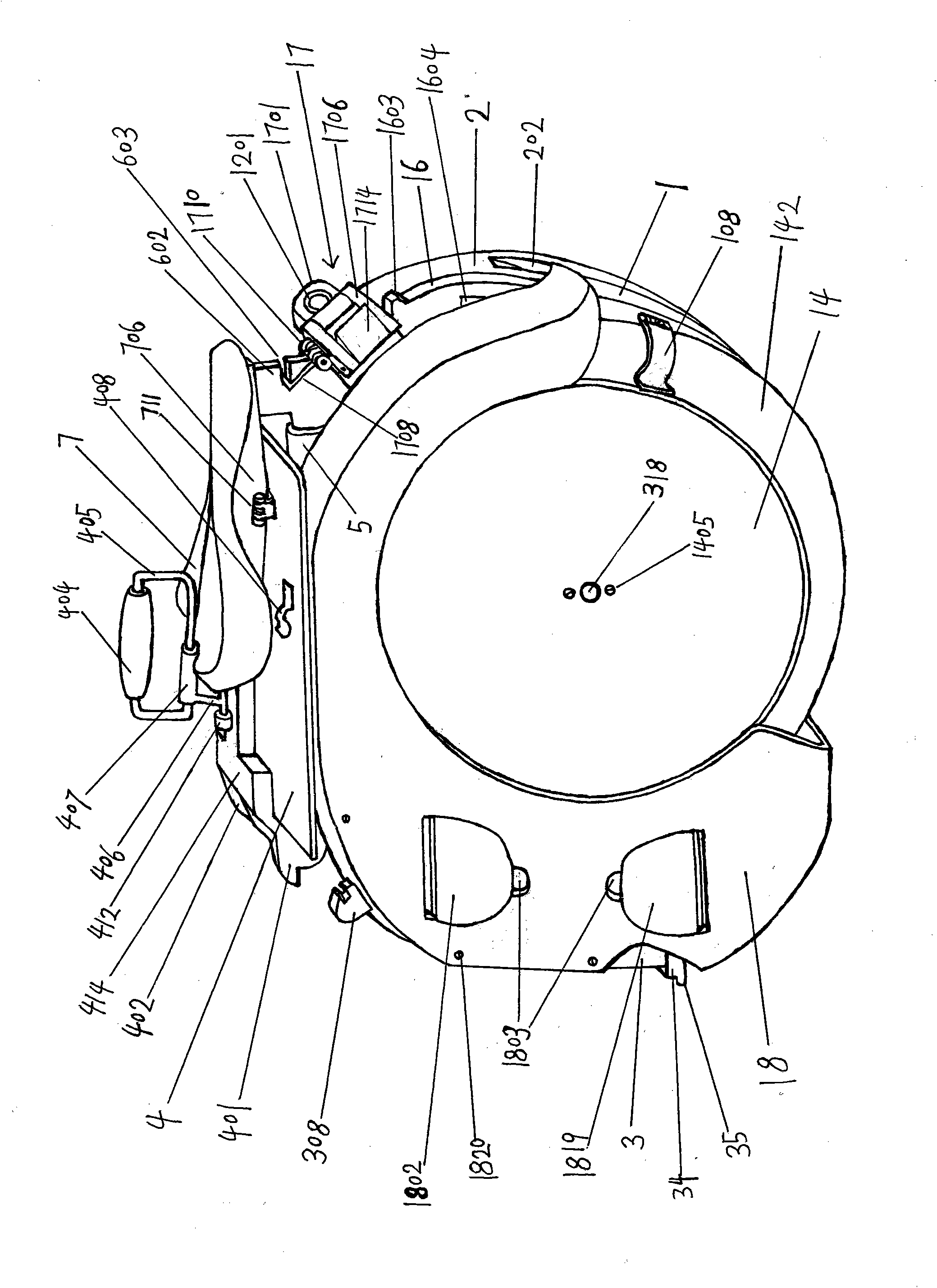
[0119] Such as figure 1 , 31 , 32, the present invention is a box-type foldable bicycle, comprising a handlebar component, a front steering component positioned below the handlebar component, and a vehicle frame component positioned behind the front steering component, wherein the handlebar component includes a left bicycle 10, the right handlebar 1009 and the folding assembly, the left handlebar and the right handlebar are installed on both sides of the folding assembly respectively, and the lower end of the folding assembly is connected with the telescopic tube 9; the folding assembly includes: chain padlock 1001, hinge 1006, cover plate 907; the stigma hole 1008 on the chain padlock 1001 is set on the top of the telescopic tube 9, and the chain padlock 1001 is fixed on the top of the telescopic tube 9 through the cover plate 907; Hinge 1006, hinge 1006 comprises two pieces of hinge plates 100...
Embodiment 2
[0133] Embodiment 2, more specific instructions:
[0134] Please refer to figure 1 figure 2 image 3, This box-type folding bicycle includes a frame beam 1, a support 16, a front wheel frame 2, a rear wheel frame 3, a loading frame 4, a wheel bracket 12, a front wheel 13, a link buckle 17, a steering tube 8, and a telescopic tube 9 , handlebar 10, handlebar 1009, rear wheel 14, rear wheel cover 18, saddle pipe 5, drop tube 6, saddle 7, crank 15, crank 1522 and car support 19; Described this car structure is as follows:
[0135] Such as Figure 18 , 1 , the frame beam 1 is U-shaped, with a central shaft frame 120 in the middle, a central shaft 11 is mounted on the central shaft frame 120, a large sprocket 1102 is fixedly connected to the central shaft 11, and a sprocket shaft 126 is installed at the rear end of the lower part of the frame beam 1 , the small sprocket 123 and the pulley 127 are fixed on the sprocket shaft 126, one side of the front end of the frame beam 1 i...
PUM
 Abstract
Description
Claims
Application Information
 - R&D
- Intellectual Property
- Life Sciences
- Materials
- Tech Scout
- Unparalleled Data Quality
- Higher Quality Content
- 60% Fewer Hallucinations
Browse by: Latest US Patents, China's latest patents, Technical Efficacy Thesaurus, Application Domain, Technology Topic, Popular Technical Reports.
© 2025 PatSnap. All rights reserved.Legal|Privacy policy|Modern Slavery Act Transparency Statement|Sitemap|About US| Contact US: help@patsnap.com


