Check patentability & draft patents in minutes with Patsnap Eureka AI!

Control of locking differential

A technology of locking differentials and differentials, which is applied in the direction of control devices, differential transmissions, transmissions, etc., and can solve problems such as single speed

Active Publication Date: 2010-10-13
FORD GLOBAL TECH LLC
View PDF8 Cites 4 Cited by
  • Summary
  • Abstract
  • Description
  • Claims
  • Application Information

AI Technical Summary

Problems solved by technology

But there are situations where it is necessary to lock the driveshafts of the front and rear axles together so that a single speed can be regained

Method used


Image

  • Control of locking differential
  • Control of locking differential
  • Control of locking differential

Examples


Embodiment Construction

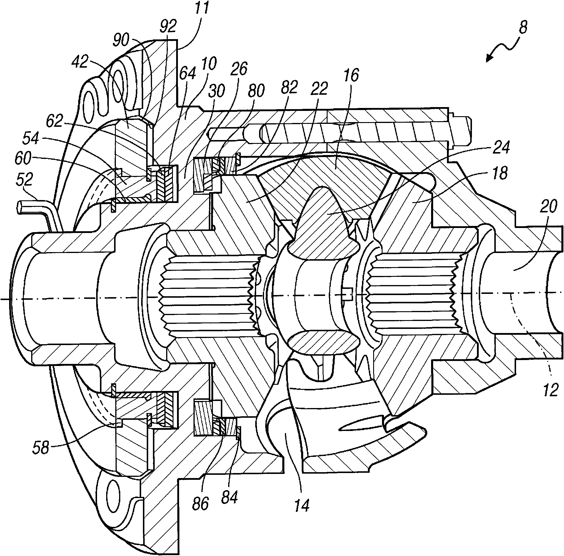
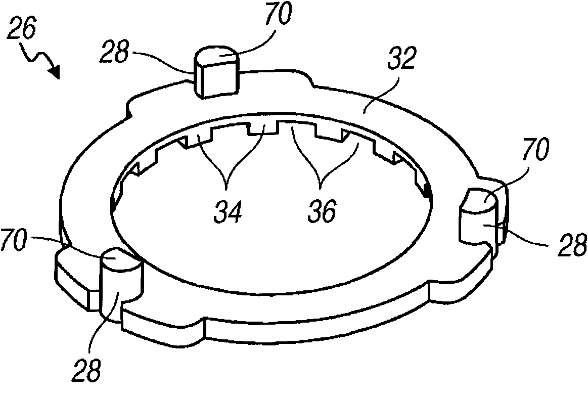
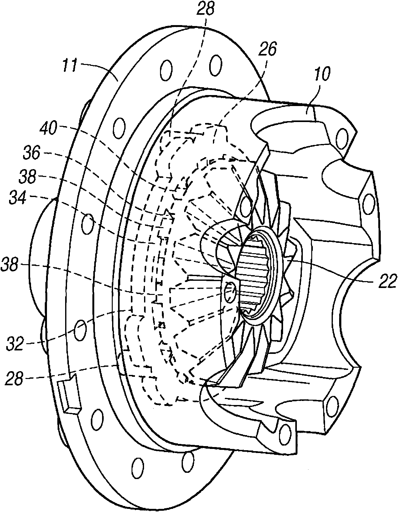
[0019] reference Figure 1 to Figure 4 The electronic locking differential 8 includes a differential case 10 preferably made of cast iron or steel, the differential case being supported on a stationary housing (not shown) so as to rotate about a transverse axis 12. The pot gear fixed to the differential case at the mounting hole of the flange 11 drives the differential case 10 to rotate around the axis 12 from the output end of the gearbox or transfer case.

[0020] The differential case 10 provides an inner cavity 14, which contains a small bevel gear 16, a right side gear that meshes with the small bevel gear and is drivingly connected to the right output shaft 20 extending from the differential case 10 to the drive wheels of the motor vehicle 18 and the left side gear 22 meshing with the pinion gear and drivingly connected with the left output shaft (not shown) of the driving wheel extending from the differential case to the left. Each small bevel gear 16 is fixed to the rota...


PUM


Abstract

A method for controlling a locking differential for a vehicle includes using a coil to unlock the differential, if the vehicle stops for a period whose length is equal to or greater than a reference length, and using the coil to lock the differential, if the vehicle is moving or stopped for less than the reference length.

Description

Technical field [0001] The present invention generally relates to a differential mechanism that transmits rotational power to the wheels of a motor vehicle and is locked to prevent the wheels from rotating at different speeds. Background technique [0002] An open differential or limited-slip differential mechanism is usually used to allow limited wheel slip at the axle, that is, to create a speed difference between the driving wheels. The purpose of the locking differential is to prevent the relative rotation of one drive wheel with respect to the other drive wheel. This is generally achieved by locking a differential side gear to the differential case, thereby preventing the side gear from rotating relative to the differential case and preventing the relative wheel speed difference at either end of the shaft. [0003] The lock-up differential can also be used as an inter-wheel differential or center differential for 4×4 and AWD (all-wheel drive) vehicles. In this case, the axis...

Claims


Application Information

Patent Timeline
IPC IPC(8): F16H48/20
CPCF16H48/24F16H48/30F16H2048/204F16H48/08F16H2048/346
Inventor J·M·波维尔克J·J·托雷斯B·J·安多尼安郭继红P·梅洛希K·G·瓦拉加
Owner FORD GLOBAL TECH LLC
Features
  • R&D
  • Intellectual Property
  • Life Sciences
  • Materials
  • Tech Scout
  • Unparalleled Data Quality
  • Higher Quality Content
  • 60% Fewer Hallucinations
Learn More