Buck chopper circuit, LED drive circuit and LED lamp

A chopper circuit and filter capacitor technology, which is applied in the direction of lamp circuit layout, electric light source, electrical components, etc., can solve problems such as limited voltage input range

Inactive Publication Date: 2010-10-13
OCEANS KING LIGHTING SCI&TECH CO LTD +1
View PDF5 Cites 14 Cited by
  • Summary
  • Abstract
  • Description
  • Claims
  • Application Information

AI Technical Summary

Problems solved by technology

[0005] The purpose of the embodiment of the present invention is to provide a step-down chopper circuit, aiming to solve the problem of limited voltage input range in the existing step-down chopper circuit

Method used


Image

  • Buck chopper circuit, LED drive circuit and LED lamp
  • Buck chopper circuit, LED drive circuit and LED lamp
  • Buck chopper circuit, LED drive circuit and LED lamp

Examples


Embodiment Construction

[0024] In order to make the object, technical solution and advantages of the present invention clearer, the present invention will be further described in detail below in conjunction with the accompanying drawings and embodiments. It should be understood that the specific embodiments described here are only used to explain the present invention, not to limit the present invention.

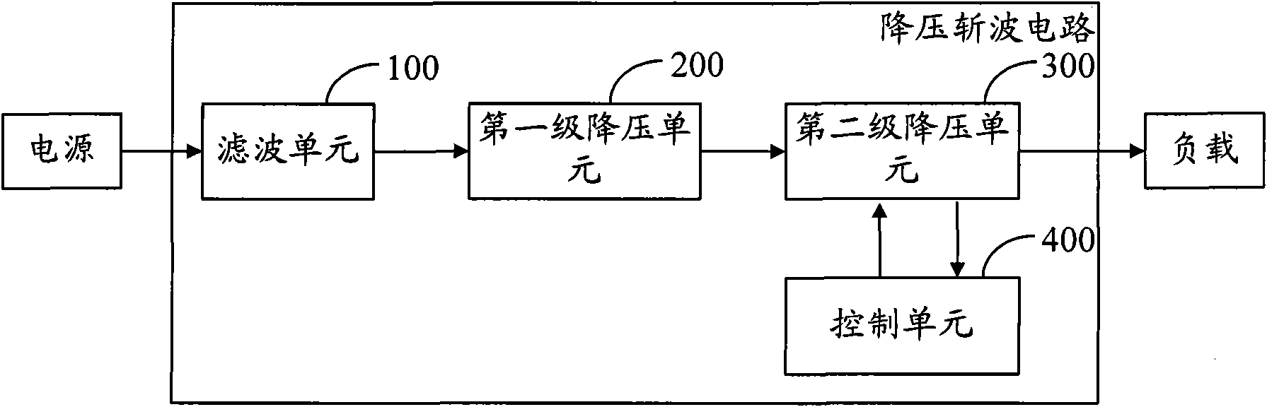
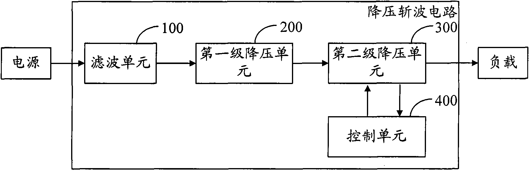
[0025] The step-down chopper circuit provided by the embodiment of the present invention has a first-stage step-down unit and a second-stage step-down unit. Compared with step-down, the input voltage can be greatly reduced. Therefore, under the premise that the output voltage remains unchanged, the step-down chopper circuit can greatly increase the voltage input range compared with the first-stage step-down circuit.

[0026] figure 1 The structure of the step-down chopper circuit provided by the embodiment of the present invention is shown, and for the convenience of description, only the parts re...


PUM


Abstract

The invention is applicable to the field of LED lamps, and provides a buck chopper circuit, an LED drive circuit and an LED lamp, wherein the buck chopper circuit comprises a filtering unit, a first-stage voltage-reducing unit, a second-stage voltage-reducing unit and a control unit. In the embodiment of the invention, the buck chopper circuit is provided with the first-stage voltage-reducing unit and the second-stage voltage-reducing unit; and compared with the adoption of one-stage voltage reduction, the adoption of two-stage voltage reduction can greatly reduce the input voltage under the condition of the same duty cycle, therefore, compared with the adoption of the one-stage voltage reduction, the adoption of the buck chopper circuit can greatly increase the input scope of the voltage under the precise that the input voltage is constant.

Description

technical field [0001] The invention belongs to the field of LED lamps, and in particular relates to a step-down chopper circuit, an LED driving circuit and an LED lamp. Background technique [0002] Step-down chopper circuit, also known as BUCK transformer, is a basic DC / DC converter that can realize step-down function in DC / DC conversion. [0003] Under the control of the PWM control signal, the step-down chopper circuit converts the input high voltage into a low voltage output. The voltage value of the output voltage is determined by the duty cycle of the PWM control signal. If the input voltage is the same, the PWM control The smaller the duty cycle of the signal, the smaller the voltage value of the output voltage; if the output voltage is the same, the smaller the duty cycle of the PWM control signal, the larger the voltage value of the input voltage. [0004] On the premise that the output voltage remains unchanged, in order to increase the input range of the voltage...

Claims


Application Information

Patent Timeline
Patent Type & Authority Applications(China)
IPC IPC(8): H02M3/06H02M3/155H05B37/02
Inventor 周明杰谭威
Owner OCEANS KING LIGHTING SCI&TECH CO LTD
Why Eureka
Try Eureka