Transformer and resonant circuit having same

Active Publication Date: 2018-08-23
ORMON CORPORATION
View PDF6 Cites 1 Cited by
  • Summary
  • Abstract
  • Description
  • Claims
  • Application Information

AI Technical Summary

Benefits of technology

The present invention provides a transformer and a resonant circuit that have the following benefits: a smaller size without additional components, reduced loss due to leakage magnetic field or proximity effect, and high leakage inductance. The resonant circuit allows for a small ratio between excitation inductance and resonant inductance, resulting in a sharp frequency characteristic and a wide range of output voltage with changes in switching frequency. This also allows for wider input range with changes in switching frequency when the output voltage is constantly controlled.

Problems solved by technology

However, when a transformer is made smaller, there is a problem that it is difficult to maintain a sufficient interval between a primary winding and a secondary winding for making leakage, and a leakage inductance required for resonance may not be obtained.
However, the leakage magnetic field from the added magnet intersects with the surrounding windings, and thereby a loss is increased.
However, in the method in which the primary winding is wound around the middle leg portion alone, the number of layers of the primary winding is increased, and efficiency is reduced by a proximity effect.

Method used


Image

  • Transformer and resonant circuit having same
  • Transformer and resonant circuit having same
  • Transformer and resonant circuit having same

Examples


first embodiment

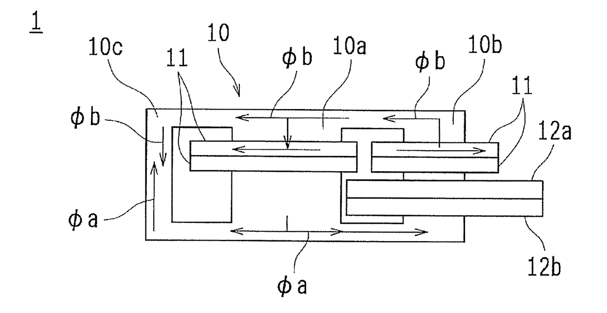
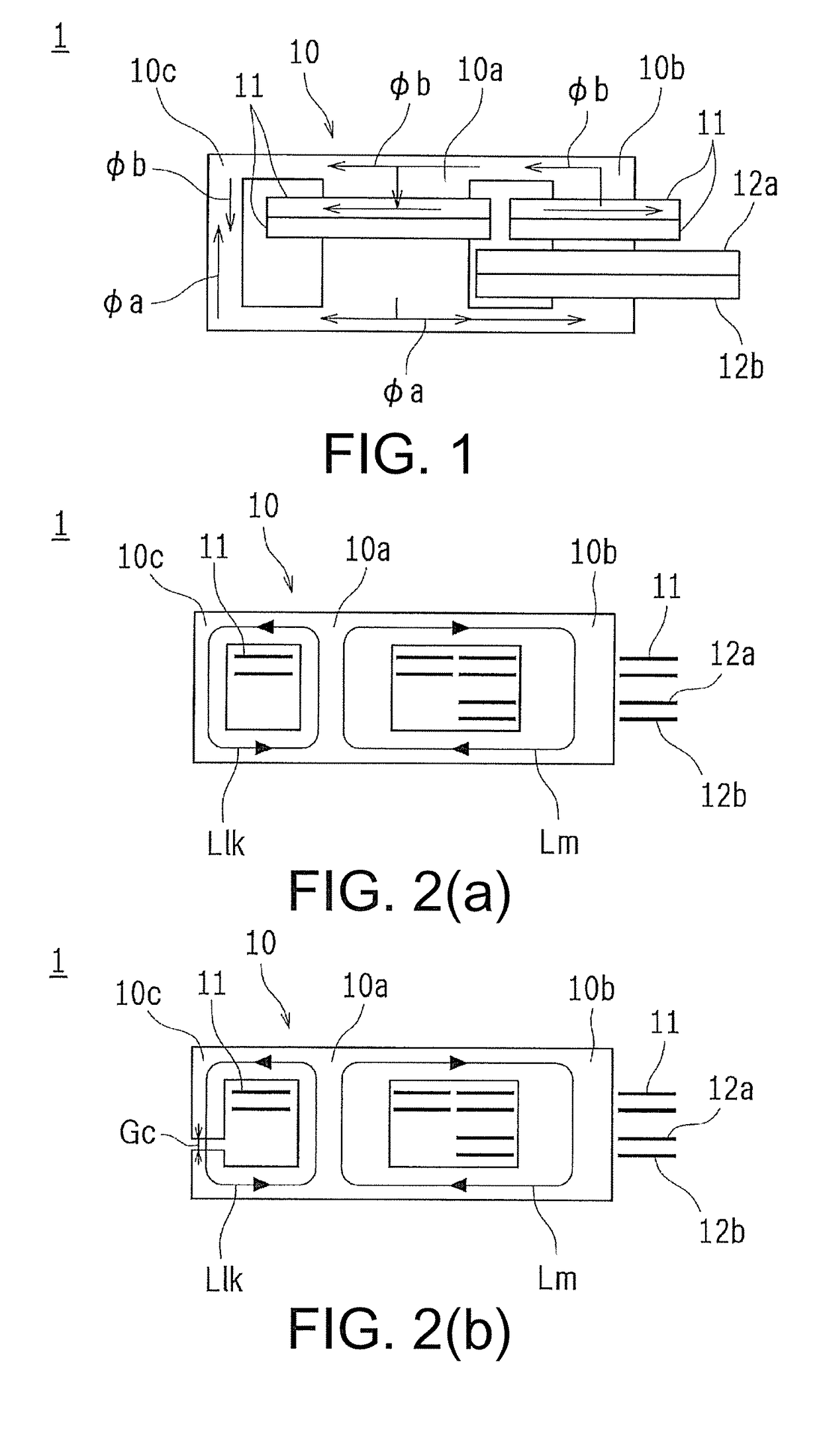
[0035]FIG. 1 is an overview configuration diagram of a transformer 1 according to a first embodiment of the present invention. FIG. 2(a) is a schematic explanatory diagram of an excitation inductance Lm and a leakage inductance Llk in the transformer 1. FIG. 2(b) is a schematic explanatory diagram of an example in which a gap is provided in a left leg 10c of a core 10 of the transformer 1.

[0036]As illustrated in FIG. 1, the transformer 1 includes a core 10 that forms a magnetic circuit, primary windings 11 that are input sides, and a secondary first winding 12a and a secondary second winding 12b (referred to collectively as a secondary winding 12) that are output sides. Here, a case in which a center tap is removed from the secondary winding 12 is shown, but if the center tap is not removed, only one of the secondary first winding 12a and the secondary second winding 12b may be used.

[0037]The core 10 has one middle leg 10a and side legs 10b and 10c branching off into two from the mi...

second embodiment

>

[0060]FIG. 8 is an overview configuration diagram of a half bridge type series resonant converter circuit 20 according to a second embodiment of the present invention.

[0061]The transformer 1 of the aforementioned first embodiment is suitable for, for instance, series resonant converter circuits of a half bridge and a full bridge, a phase shift full bridge circuit, a dual active bridge (DAB) circuit, or the like.

[0062]It can be used in a resonant circuit that uses the resonance of a resonant inductance Lr and a resonant capacitor Cr which are connected in series to an excitation inductance of the transformer 1. An example of the resonant circuit is the half bridge type series resonant converter circuit 20 illustrated in FIG. 8.

[0063]According to this second embodiment, the transformer 1 of the first embodiment which has a high leakage inductance is used, and thereby a series resonant converter in which a ratio (I=Lm / Lr) between the excitation inductance Lm and the resonant inductanc...

first example

[0065]FIG. 9 is an overview configuration diagram of a core 10 of a first example of the first embodiment of the present invention. In the first example, as illustrated in FIG. 9, a core 10 was used in which a cross-sectional area Ac of the left leg 10c for a leakage inductance path was set to 1, a cross-sectional area Aa of the middle leg 10a was set to 2, and a cross-sectional area Ab of the right leg 10b was set to 2.

[0066]The primary winding 11 was alternately wound around the middle leg 10a and the right leg 10b of the core 10 in the number 8 by two turns for the middle leg and one turn for the right leg for a total of 15 turns (ten turns of the middle leg and five turns for the right leg), and finally one turn for the right leg.

[0067]Further, the secondary winding 12 was wound around the right leg 10b of the core 10 in the same direction as the primary winding 11 by two turns, and aside from this, the secondary winding 12 was wound around the right leg 10b in the direction opp...


PUM


Abstract

Provided is a transformer (1), which includes: a core (10) which forms a magnetic circuit and has a middle leg (10a) and a plurality of side legs (10b, 10c) branched from the middle leg (10a); primary windings (11) respectively wound around a first winding leg (10a) and a second winding leg (10b), which are selected from the middle leg (10a) and the side legs (10b, 10c); and a secondary winding (12) wound around either of the first winding leg (10a) or the second winding leg (10b), wherein a first magnetic flux generated by the primary windings (11) from the first winding leg (10a) and a second magnetic flux generated by the primary windings (11) from the second winding leg (10b) differ from each other by a predetermined value or more at a position at which the fluxes do not intersect with the secondary winding (12).

Description

TECHNICAL FIELD[0001]The present invention relates to a small transformer (a transformer) having a high leakage inductance used in a resonant circuit, and a resonant circuit having the same.BACKGROUND ART[0002]Conventionally, a resonant circuit realizes soft switching using the resonance of a resonant inductance Lr and a resonant capacitor Cr. A leakage inductance of a transformer can be used in the resonant inductance Lr. It is known that, with use of the leakage inductance, the number of parts is reduced, and noise can be reduced.[0003]However, when a transformer is made smaller, there is a problem that it is difficult to maintain a sufficient interval between a primary winding and a secondary winding for making leakage, and a leakage inductance required for resonance may not be obtained.[0004]Thus, to obtain a high leakage inductance, a method using a bobbin that separates a primary winding from a secondary winding has been proposed (e.g., see Patent Literature 1).[0005]However, ...

Claims


Application Information

Patent Timeline
IPC IPC(8): H01F38/08H01F27/24H01F27/28H01F27/34H01F3/14
CPCH01F38/08H01F27/24H01F27/28H01F27/346H01F3/14H01F3/12H01F27/38Y02B70/10H02M1/0058H02M1/0064H02M3/003H02M3/33571H02M3/01
Inventor NAGAOKA, SHINGOZAITSU, TOSHIYUKIOKUNO, YUTAROMORISHITA, SADAHARU
Owner ORMON CORPORATION
Why Eureka
Try Eureka