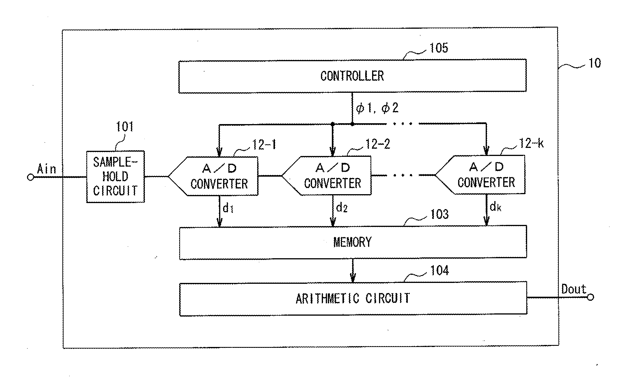
Pipeline type a/d converter

Active Publication Date: 2011-10-06
ASAHI KASEI ELECTRONICS CO LTD
View PDF5 Cites 2 Cited by
  • Summary
  • Abstract
  • Description
  • Claims
  • Application Information

AI Technical Summary

Benefits of technology

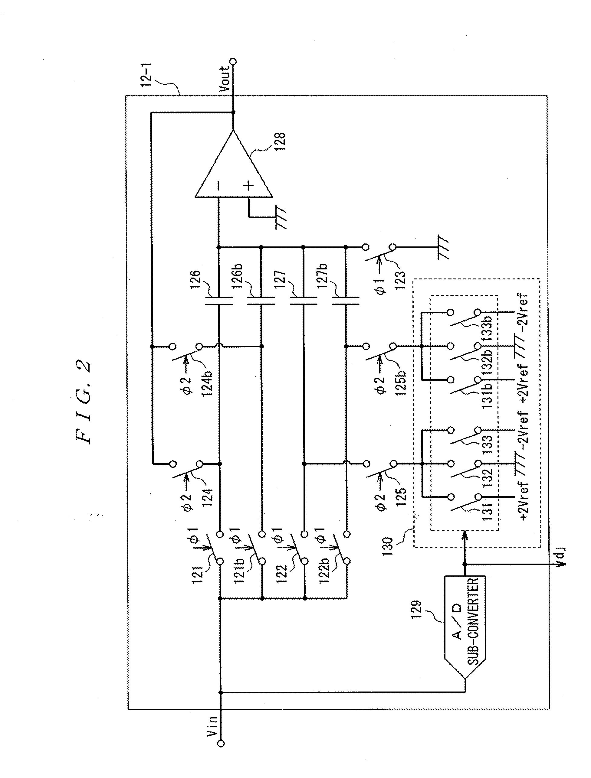
[0075]According to the present invention, all the N×M charge and discharge elements are used as the charge and discharge elements to sample the analog signal. Herein, M denotes an amplification degree of the analog signal and N denotes the number of division of the charge and discharge elements compared with the prior art. When N=1, it designates the number of the charge and discharge elements in the case where the range is not expanded in the prior art. Since all the charge and discharge elements operate for sampling of the analog signal, an increase in the thermal noises does not occur as compared with the case where the range is not expanded in the prior art. Furthermore, N charge and discharge elements each are used as a feedback element to amplify the analog signal, whereas the remaining N×(M−1) charge and discharge elements are used for addition and subtraction of the reference voltage. On that account, since the ratio of the capacitance of the remaining charge and discharge elements to that of the charge and discharge elements each used as the feedback element is unchanged, the amount of feedback does not decrease, the open loop gain needed for the operational amplifier will not be increased as compared with the case where the range is not expanded in the prior art.
[0076]Nevertheless, increasing the number of division N permits increasing the number of the freely controllable charge and discharge elements, which expands the input range of the pipeline type A / D converter, without increasing thermal noises and the open loop gain needed for the operational amplifier.

Problems solved by technology

In other words, the increase in number of the capacitors which are not involved in sampling of the analog signal Vin entails a problem of increasing the thermal noises of the pipeline type A / D converter 100.
In order to increase the open loop gain of the operational amplifier, it usually brings with an increase in power consumption and an increase in area of the pipeline type A / D converter.
Refinement process poses a problem that it is difficult to achieve the high open loop gain itself with a reduced power supply voltage.

Method used


Image

  • Pipeline type a/d converter
  • Pipeline type a/d converter
  • Pipeline type a/d converter

Examples


first modification

(First Modification)

[0124]The A / D converters 12-1 to 12-k of the pipeline type A / D converter 10 according to the present embodiment are responsible for resolution of 1.5 bits (in this case, input signal is doubly amplified). When the number of division of the capacitors is 2 (i.e., N=2), a capacitor to be divided is not necessarily limited to the sample-hold capacitor.

[0125]FIG. 4 is a circuit diagram showing a circuit configuration of the A / D converter 22-1 when its resolution is 1.5 bits (in this case, input signal is doubly amplified) and the number of division of the capacitors is 1 (i.e., N=1).

[0126]While the A / D converter 12-1b shown in FIG. 4 is a circuit configured with the same elements as those of the A / D converter 12-1 shown in FIG. 2, they are different in that the multiple-value output circuit 130 outputs one of voltages from −2×Vref (V), 0V, and +2×Vref (V). In other words, when the number of division is 1 (N=1), the multiple-value output circuit 130 multiples one of v...

second modification

(Second Modification)

[0133]While the pipeline type A / D converters 12-1 to 12-k according to the present embodiment has the configuration in which the resolution is 1.5 bits (in this case, the input signal is doubly amplified) and the number of division of comparators is 2 (i.e., N=2), the number of division of the comparators is not necessarily limited to 2.

[0134]FIG. 5 is a circuit diagram showing a circuit configuration in which the resolution is 1.5 bits (in this case, input signal is doubly amplified) and the number of division of the comparator is 2 (i.e., N=3).

[0135]Although the A / D converter 12-1c shown in FIG. 5 is a circuit configured with the same elements as those of the A / D converter 12-1 shown in FIG. 2, they are different in that the A / D converter 1201c further includes the sample-hold switching elements 121c, 122c, 124c, and 125c, the A / D converter 12-1c includes sample-hold capacitors 126c and 127c, and the multiple-value output circuit 130 includes three switching e...

third modification

(Third Modification)

[0143]Although the A / D converters 12-1 to 12-k of the pipeline type A / D converter 10 according to the present embodiment has the configuration in which the resolution is 1.5 bits (in this case, the input signal is doubly amplified), the resolution is not necessarily limited to 1.5 bits.

[0144]FIG. 7 is a circuit diagram showing a circuit configuration in which the resolution is 2.5 bits (in this case, the input signal is fourfold amplified) and the number of the comparators is 2 (i.e., N=2).

[0145]The A / D converter 12-1d shown in FIG. 7 is a circuit configured with the same circuit configuration as those of the A / D converter 12-1 shown FIG. 12, and they are different in that the A / D converter 12-1d further includes sample-hold switching elements 122c to 122f, and 125c to 125f, sample-hold capacitors 127c to 127f, and the multiple-value output circuit 130 includes eighteenth switching elements 131c to 131f, 132c to 132f, and 133c to 133f. In other words, the A / D con...


PUM


Abstract

There is provided a pipeline type A / D converter capable of expanding an input range and increasing the number of bits of digital output signals, without increasing thermal noises or an open loop gain needed for an operational amplifier. The number of sample-hold capacitors is divided from M into N and further multiplies the reference voltage by N to increase the number of capacitors available to add to and subtract from the reference voltage. Consequently, it enables expanding the input range and increasing the number of bits of the digital output signals. On this occasion, the thermal noises are not deteriorated before and after the division of the capacitors, as the analog signal is sampled by all the capacitors. Further, the open loop gain needed for the operational amplifier will not be increased, since the ratio of the capacitors each used as a feedback element for amplifying the analog signal to the remaining capacitors is unchanged before and after the division of the capacitors.

Description

TECHNICAL FIELD[0001]The present invention relates to an A / D converter, in particular, to a pipeline type A / D converter in which input range and bit rate of digital output are increased.BACKGROUND ART[0002]Electronic devices, such as various image sensors and image processing equipments etc., which are under the necessity of converting analog signals into digital signals are required to do high speed processing of a large amount of data. As an A / D converter permitting to handle such processing, there has been known heretofore a pipeline type A / D converter configured by connecting cascade connected plural A / D converters to allow multiple A / D converting processing for one clock.[0003]A conventional pipeline type A / D converter includes, e.g., a pipeline type A / D converter disclosed in Non-Patent Document 1.[0004]Firstly, a description will be made to a configuration of the conventional general pipeline type A / D converter referring to the FIG. 10. FIG. 10 is a block diagram showing the ...

Claims


Application Information

Patent Timeline
IPC IPC(8): H03M1/12
CPCH03M1/164
Inventor EGAWA, KAZUKI
Owner ASAHI KASEI ELECTRONICS CO LTD
Why Eureka
Try Eureka