Directional microphone device

Active Publication Date: 2011-07-14
PANASONIC CORP
View PDF7 Cites 10 Cited by
  • Summary
  • Abstract
  • Description
  • Claims
  • Application Information

AI Technical Summary

Benefits of technology

[0044]According to the present invention, it is possible to suppress the problem of increase in the thermal noise (problem of decrease in sensitivity) that occurs at the time of directivity synthesis, and to achieve a directional microphone device with high sensitivity. In other words, the directional microphone device of the present invention, which performs directivity synthesis of sound-pressure gradient type in which directivity is obtained through synthesis of signals from plural microphones, can obtain favorable microphone directivity without degradation of sensitivity (without increase in the thermal noise level).

Problems solved by technology

While the directivity synthesis method of the sound-pressure gradient type has an advantage that a small directional microphone device can be achieved, the method has a disadvantage that sound pressure sensitivity is decreased when signals are synthesized.
This results in deterioration of signal to noise ratio (S / N).
Particularly, when directivity synthesis of the sound-pressure gradient type is performed on output signals from plural microphone units, influences of the thermal noise cannot be ignored, which imposes low-frequency limit of frequency range having directivity and limitation in miniaturization of microphone array.
However, for example, in the case where two microphone units are used for the small directional microphone device 1 with the spacing d of approximately 10 mm between the microphone units, the thermal noise level, as described earlier, increases by 30 dB (at 100 Hz) due to directivity synthesis.
As a result, small sound is buried in the thermal noise, thereby not being perceived (sensitivity is decreased).
This causes practical issues.

Method used


Image

  • Directional microphone device
  • Directional microphone device
  • Directional microphone device

Examples


first embodiment

[0119]FIG. 6 is a block diagram showing a structure of a directional microphone device 1000 according to the first embodiment of the present invention.

[0120]The directional microphone device 1000 includes: a first microphone unit 11; a second microphone unit 12; a signal-synthesis sensitivity-increase unit 20; a directivity synthesis unit 30; a mix ratio calculation unit 40; a first signal amplification unit 50; a second signal amplification unit 60; a signal addition unit 70; and an output terminal 80.

[0121]In FIG. 6, the first microphone unit 11 and the second microphone unit 12 are arranged such that the first microphone unit 11 is positioned closer to target sound (sound source A) and the second microphone unit 12 is positioned closer to non-target sound (sound source B).

[0122]The signal-synthesis sensitivity-increase unit 20 receives output signal m1 from the first microphone unit 11 and output signal m2 from the second microphone unit 12, and synthesize the signals so that sou...

second embodiment

[0161]FIG. 13 is a block diagram showing a structure of a directional microphone device 1001 according to the second embodiment of the present invention.

[0162]The directional microphone device 1001 includes: a first microphone unit 11; a second microphone unit 12; a signal-synthesis sensitivity-increase unit 20; a directivity synthesis unit 30; a signal subtraction unit 71; an output terminal 80; and a noise suppression unit 100.

[0163]In FIG. 13, the first microphone unit 11 and the second microphone unit 12 are arranged such that the first microphone unit 11 is positioned closer to a target sound (sound source A) and the second microphone unit 12 is positioned closer to a non-target sound (sound source B).

[0164]The signal-synthesis sensitivity-increase unit 20 receives an output signal m1 from the first microphone unit 11 and an output signal m2 from the second microphone unit 12, and synthesizes the signals so that sound pressure sensitivity of the directional microphone device 10...

third embodiment

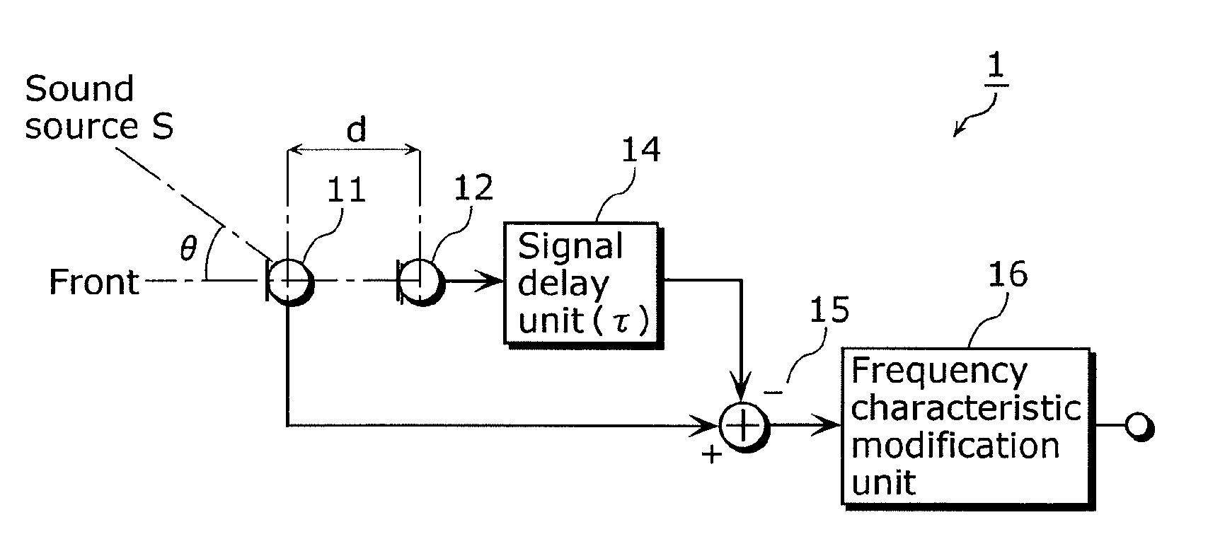
[0188]FIG. 18 is a block diagram showing a structure of a directional microphone device 1002 according to the third embodiment of the present invention.

[0189]In FIG. 18, the directional microphone device 1002 includes a first microphone unit 11 and a second microphone unit 12. Further, the directional microphone device 1002 includes: a signal addition unit 22; a signal amplification unit 23; a signal subtraction unit 32; a frequency characteristic modification unit 33; a signal delay unit 41; a signal subtraction unit 71; an output terminal 80; and a noise suppression unit 100.

[0190]Note that in the following description, it is assumed that on a straight line connecting the first microphone unit 11. and the second microphone unit 12, the first microphone unit 11 side is front, and the second microphone unit 12 side is rear.

[0191]The signal delay unit 41 delays an output signal from the first microphone unit 11 and provides the resulting signal.

[0192]The signal addition unit 22 adds ...


PUM


Abstract

The directional microphone device according to the present invention solves a problem of increase in thermal noise (problem of decrease in sensitivity) that occurs at the time of directivity synthesis. The directional microphone device includes: a plurality of microphones which have directional and non-directional characteristics; a control unit which generates an output signal using signals outputted from each of the plurality of microphones; and an output unit which outputs the output signal generated by the control to unit. The control unit generates the output signal such that a nearly non-directional directivity and a high sensitivity are obtained in small amplitude range of the output signal, and a directivity and a low sensitivity are obtained in large amplitude range of the output signal.

Description

TECHNICAL FIELD[0001]The present invention relates to directional microphone devices, and particularly to a directional microphone device which performs directivity synthesis of a sound-pressure gradient type and is widely used not only as a built-in microphone, but also as a general directional microphone.BACKGROUND ART[0002]There is a directional microphone device which is a sound-pressure gradient type and is widely used not only as a built-in microphone, but also as a general directional microphone. While the directivity synthesis method of the sound-pressure gradient type has an advantage that a small directional microphone device can be achieved, the method has a disadvantage that sound pressure sensitivity is decreased when signals are synthesized. In the directivity synthesis method of the sound-pressure gradient type, microphone sensitivity decreases with respect to the thermal noise level of a microphone unit and a microphone amplifier at the time of synthesis of the signa...

Claims


Application Information

Patent Timeline
IPC IPC(8): H04R3/00
CPCH04R3/005
Inventor KANAMORI, TAKEO
Owner PANASONIC CORP
Why Eureka
Try Eureka