
Circuit for cancelling pulse interference

A technology to eliminate circuit and pulse interference, applied in pulse shaping and other directions, can solve problems such as inability to use diodes, inability to accurately control DC transition points, and inability to accurately control time.

Active Publication Date: 2012-12-12
FARADAY TECH CORP
View PDF0 Cites 0 Cited by
  • Summary
  • Abstract
  • Description
  • Claims
  • Application Information

AI Technical Summary

Problems solved by technology

[0008] The second is that it is generally impossible to use an ideal diode in actual operation. If a Metal Oxide Semiconductor (MOS) transistor is used as a unidirectional diode, there will still be a small reverse current, and the reverse current It will cause the DC transition point to be unable to be accurately controlled
In general high-speed transmission systems, there are specifications for the DC transition point and the AC transition point. If you want to use the peak detector 300 to avoid the problem of pulse interference, the DC transition point and the AC transition point will be different in design. more difficult
Moreover, the transmission system will have transmission delay specifications, and the use of the peak detector 300 cannot accurately control the transmission delay time
Therefore, although the peak detector 300 can achieve the elimination of pulse interference, it will affect the design of other specifications of the transmission system, so that there are still many restrictions on application
[0009] It can be seen that the above-mentioned existing pulse interference elimination circuit obviously still has inconvenience and defects in structure and use, and needs to be further improved urgently.
In order to solve the above-mentioned problems, the relevant manufacturers have tried their best to find a solution, but for a long time no suitable design has been developed, and the general product has no suitable structure to solve the above-mentioned problems. This is obviously the relevant industry. Urgent problem

Method used


Image

  • Circuit for cancelling pulse interference
  • Circuit for cancelling pulse interference
  • Circuit for cancelling pulse interference

Examples


Embodiment Construction

[0044] In order to further explain the technical means and effects that the present invention adopts to achieve the intended purpose of the invention, the specific implementation, structure, characteristics and effects of the pulse interference elimination circuit proposed according to the present invention will be described below in conjunction with the accompanying drawings and preferred embodiments. , as detailed below.

[0045] The aforementioned and other technical contents, features and effects of the present invention will be clearly presented in the following detailed description of the preferred embodiments with reference to the drawings. Through the description of the specific implementation mode, a more in-depth and specific understanding of the technical means and effects adopted by the present invention to achieve the intended purpose can be obtained. However, the accompanying drawings are only for reference and description, and are not used to explain the present ...


PUM


Abstract

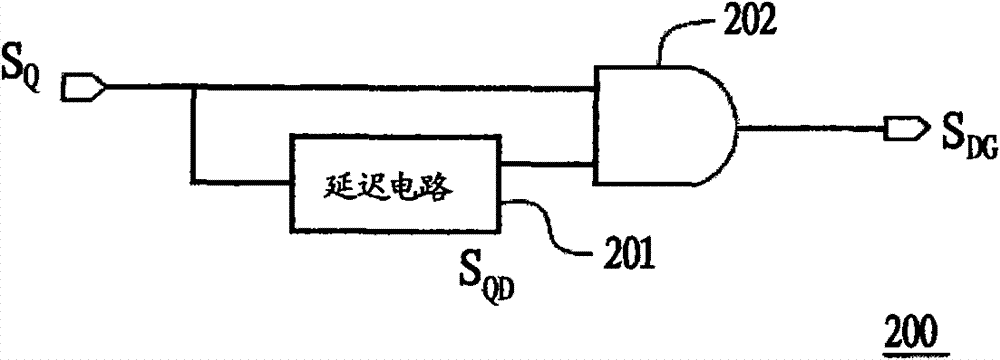
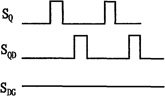
The invention relates to a circuit for cancelling pulse interference, comprising multiple signal transmission units, wherein all signal transmission units are connected in series to form a signal transmission unit string of which the first signal transmission unit receives digital signals, each signal transmission unit comprises a first switch, a first delay circuit and a second switch, the firstend of the first switch is coupled to the previous signal transmission unit in the signal transmission string, the input end of the first delay circuit is coupled to the second end of the first switch, and the second switch is coupled between the output end of the first delay circuit and a first voltage. When the digital signal is a first logic, the first switch is disconnected while the second switch is connected; and when the digital signal is a second logic, the first switch is connected while the second switch is disconnected.

Description

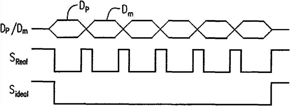
technical field [0001] The invention relates to an elimination circuit, in particular to a pulse interference elimination circuit. Background technique [0002] In high-speed wired transmission systems, such as universal serial bus (universal serialbus, USB), PCI-E or serial advanced technology attachment (serial advanced technology attachment, SATA), the receiving end usually uses a high-speed comparator to judge Whether the received data signal is valid data or noise. If the differential amplitude of the data signal is greater than the reference voltage and is judged as "data" by the comparator, the comparator may output "0" to indicate that the data signal at this time is valid data. On the contrary, if the differential amplitude of the data signal is smaller than the reference voltage and is judged as "noise" by the comparator, the comparator outputs "1" to indicate that the data signal at this time is noise. [0003] figure 1 Generate schematic diagrams for existing ...

Claims


Application Information

Patent Timeline
Patent Type & Authority Patents(China)
IPC IPC(8): H03K5/01
Inventor 黄鼎钧陈冠宇张原熏
Owner FARADAY TECH CORP
Learn More