
An extraction device and method for synchronous clock

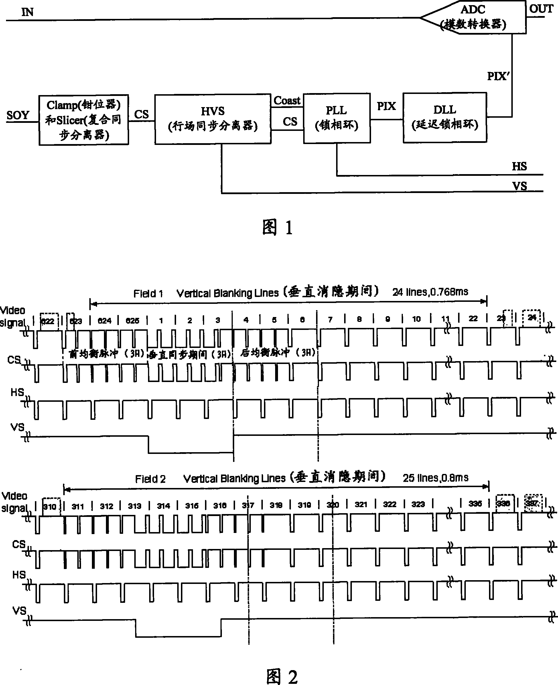
A technology of synchronous clock and extraction device, which is applied in the direction of TV, automatic power control, color TV parts, etc., can solve the problems of affecting PLL work, PLL out of lock, and inability to obtain pixel clock, etc., to achieve the effect of eliminating pulse interference

Active Publication Date: 2011-02-02
HUAWEI TECH CO LTD
View PDF0 Cites 0 Cited by
  • Summary
  • Abstract
  • Description
  • Claims
  • Application Information

AI Technical Summary

Problems solved by technology

[0007] Usually, video signals for practical applications are easily disturbed, especially CVBS signals
After the interfered video signal is processed by the composite sync separator, the obtained composite sync signal will have more pulse interference. If the composite sync signal is subjected to pulse interference, it will directly affect the PLL work, and even cause the PLL to lose lock, so that the pixel clock cannot be obtained.

Method used


Image

  • An extraction device and method for synchronous clock
  • An extraction device and method for synchronous clock
  • An extraction device and method for synchronous clock

Examples


Embodiment Construction

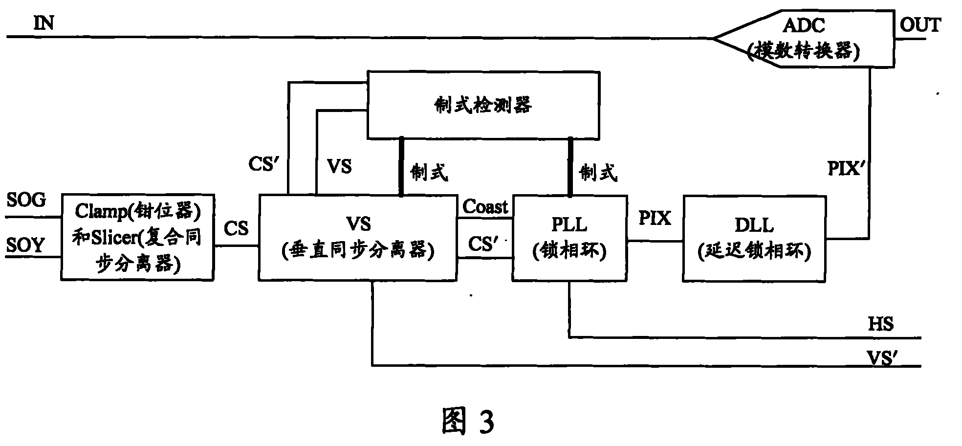
[0026] The first embodiment of the present invention provides a synchronous clock extraction device, its structural block diagram is as follows image 3 As shown, including: clamper and composite sync separator, vertical sync separator, standard detector, phase-locked loop and delay-locked loop.

[0027] The above-mentioned clamper is used for recovering a DC component from an interference signal embedded with a synchronization signal (eg, a video signal), and sending the interference signal including the recovered DC component to the composite sync separator.

[0028] The composite synchronous separator is used to compare the level of the signal output by the clamper with the set separation level, and obtain the interfering composite synchronous signal according to the comparison result.

[0029] Taking the interfering SOY signal embedded in synchronization as an example, the clamper restores the DC component of the SOY signal, and the compound sync separator combines the lev...


PUM


Abstract

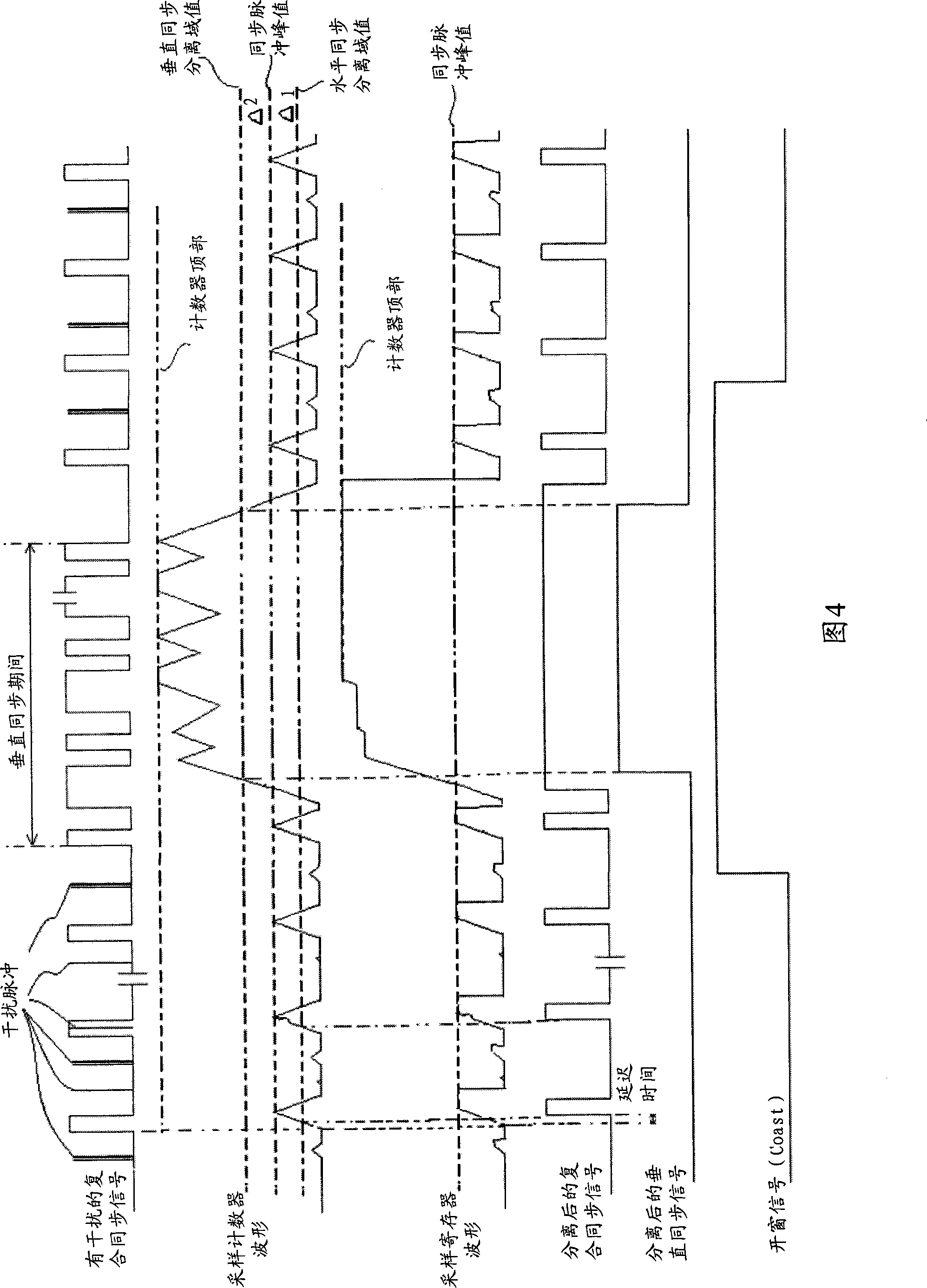
The invention discloses extraction equipment of a synchronous clock and a method thereof. The invention obtains a horizontal synchronization separation threshold defined by the standard format of a signal and a sampling clock frequency through a vertical synchronization separator; compares the horizontal synchronization separation threshold with a sampling counting value of an interference complex signal to obtain a delay complex synchronization signal after eliminating the interference according to the compared result. Therefore, the invention is capable of eliminating a pulse interference existing possibly in the signal. The invention phase demodulates a first signal and the delay complex synchronization signal to generate a control voltage according to the phase demodulation result, a control oscillator to generate a pixel clock signal and the pixel clock signal undergoes frequency division according to a frequency division ratio defined by the standard format of the signal to obtain the horizontal synchronization signal through a phase-locked loop, wherein the first signal is obtained by delay handling the horizontal synchronization according to the horizontal synchronization separation threshold and is capable of offsetting the delayed time caused by eliminating the pulse interference in the synchronization signal.

Description

technical field [0001] The present invention relates to the field of communication and computer, in particular to clock processing technology. Background technique [0002] The synchronous clock signal required by the video image includes a horizontal synchronous signal (also called a horizontal synchronous (Horizontal Sync, HS) signal) and a vertical synchronous signal (also called a vertical synchronous (VerticalSync, VS) signal). Among them, the horizontal synchronization signal controls the scan line change, and the vertical synchronization signal controls the scan field change, such as 864 * The signal in 625i@50Hz format needs to scan 50 fields per second controlled by the vertical synchronization signal, and 312.5 lines are required to be scanned by the line synchronization signal to control one field, so the line frequency of the signal is 312.5*50=15.625KHz. The synchronous clock signal can also be used to generate a sampling clock required by an Analog-Digital Con...

Claims


Application Information

Patent Timeline
Patent Type & Authority Patents(China)
IPC IPC(8): H04N5/08H03L7/18
Inventor 熊俊
Owner HUAWEI TECH CO LTD
Learn More