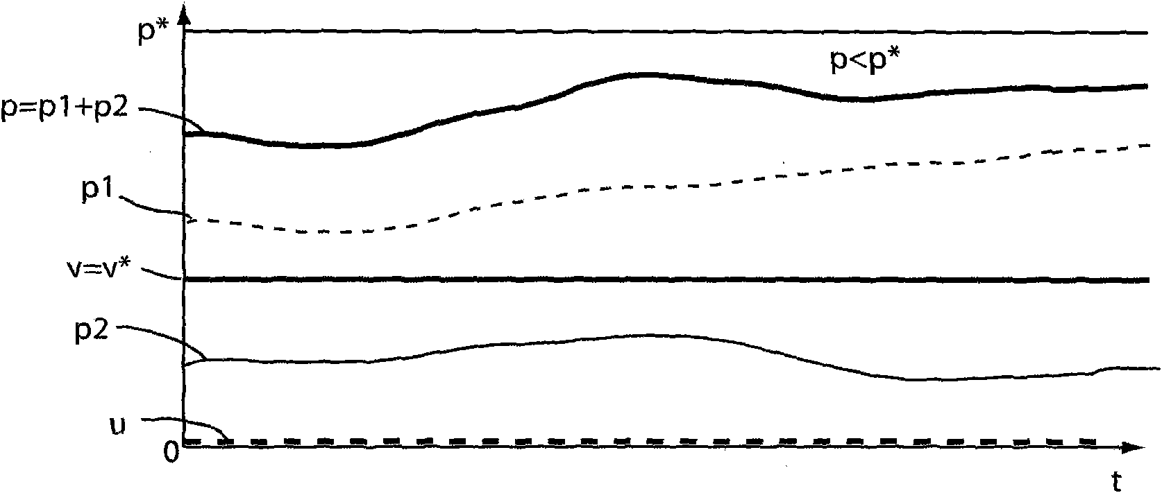
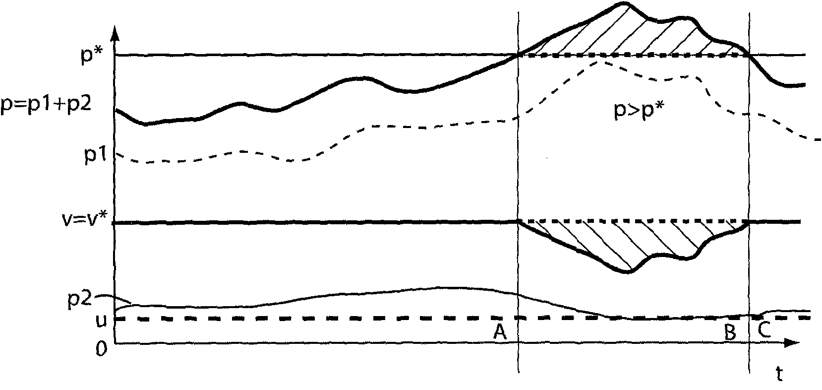
[0087] figure 1 with figure 2 The driving schematic diagram of the electric lawn mower of the present invention changing with time t is disclosed. Except for the control unit, the lawn mower of the present invention has a traditional structure and includes an electric blade motor for rotating and driving the cutting blades. The blade motor is operatively connected to a battery; used to drive the lawn mower along the lawn that needs to be trimmed The electric drive motor is operatively connected to the battery. Reference Figure 4 to Figure 7 As will be described, the present invention provides a control unit and associated components for controlling the movement of the lawn mower through the blade motor and the driving motor. Preferably, the electric drive motor acts on at least one rear wheel.
[0088] In order to more easily explain the purpose of the present invention, in figure 1 In, it is set that the operator does not push the lawnmower, so the operator does not perform auxiliary operations on the lawnmower, then u=0. The role of the operator’s thrust is figure 2 Show in. in figure 1 with figure 2 In the figure, the thrust of the operator (the energy of the operator) is represented by a dotted line u.
[0089] Just to explain the purpose of the present invention more easily, in figure 2 , The thrust u of the operator is set to be constant within the range of time t. One of the main points of the present invention is that the lawn mower works at a constant working speed or moving speed v, where v=v * , V represents the actual speed of the drive motor, v * Represents the predetermined speed of the drive motor. figure 1 For the entire time period of figure 2 In time period A and time period C, the lawn mower works at a constant speed v.
[0090] See Figure 4 to Figure 7 As shown, in order to achieve the purpose of the invention, the operator will use the motion speed selector 14 to set a predetermined speed v * Set or adjust. The operator will choose a predetermined speed v that he or she feels comfortable with * To work, even uneven, sloped lawns, and/or changes in lawn height will be taken into consideration. Predetermined speed v * The choice of will cause the control unit to be independent of the load of the lawnmower, and adjust the actual speed v of the lawnmower to the predetermined speed v *. It should be emphasized that the lawn mower maintains the working speed v=v * Even when the load of the lawn mower increases, for example, due to the appearance of a small hill, the hill has a higher lawn height that needs to be trimmed.
[0091] The drive motor needs to transmit the energy of the drive motor to the lawn mower within the range of time t. figure 1 with figure 2 The curve p2 in represents. The blade motor needs to transmit the energy of the blade motor to the blade within the range of time t, which is determined by Figure 1 to Figure 3 The middle curve p1 represents.
[0092] in figure 1 In, set the total energy p (p=p1+p2) never exceeds a predetermined maximum energy value p * (The predetermined highest energy value p * Will cause damage to the battery). But, in figure 2 Set the operator to add some thrust u to the total energy p(p=p1+p2), then the total energy p(p=p1+p2) is in the time period B instead of the adjacent time period A And C, will exceed the predetermined maximum energy value p *. The predetermined highest energy value p * The transcendence will be monitored. As a result of this conversion, the control unit will reduce the constant predetermined speed v * , For example, in the time period B, the actual speed v will follow the predetermined speed v * , And the total energy p will fall to the predetermined maximum energy value p *. In the time period B, this drop of the total energy p is represented by a dotted line. The above measures can effectively protect the battery.
[0093] The more thrust u applied by the operator, the more energy increases, the more the value p2 will drop, and the total energy p(p=p1+p2) will also decrease accordingly.
[0094] In other words: in figure 2 , Set in the time period B, the total energy p (p=p1+p2) will exceed the predetermined maximum energy value p * , This may damage the life of the battery, so in the entire time period B, the highest predetermined speed v * Reduced by the control unit, the highest predetermined speed v * The decrease of is represented by the curve under the shaded area. In the time period C, the energy value p (p=p1+p2) is reduced to the predetermined highest energy value p * Below, such as at the predetermined highest energy value p * The continuous line below is shown. Therefore, in the time period C, the control unit sets the predetermined speed v * Raise to the previously set height shown in time period A.
[0095] From figure 2 It can be seen that the energy p2 of the drive motor is much smaller than the energy p1 of the blade motor. Therefore, as figure 2 An approximation of the ideal method shown, ignoring the energy p2 of the drive motor and using the energy p1 of the blade motor alone can meet the requirements for controlling two motors. The above method is the basis of the second embodiment of the present invention image 3 Clarified.
[0096] See image 3 As shown, in the second embodiment of the present invention, a predetermined maximum blade motor energy value p1 is provided * , The predetermined maximum blade motor energy value p1 * This represents the safety value of the battery. In this embodiment, as long as the energy consumption p1 of the blade motor exceeds the predetermined maximum blade motor energy value p1 * , The predetermined speed v * Will decrease. This situation occurs in the time period E, and in the adjacent time areas D and F, the predetermined speed v * Keep it constant. in image 3 In, the predetermined speed v * The decrease of is caused by the curve V(t)=v in the time period E * (t) is indicated by the lower continuous line of the shaded area.
[0097] In an approximate way, the predetermined highest blade motor current value i1 * Replace the preset maximum blade motor energy value p1 * , Which is used to determine the predetermined speed v * The time period E that will be reduced.
[0098] See Figure 4 As shown, a lawn mower 2 includes a battery 4 for powering a drive motor 6 and a blade motor 8. The control of the first direct current i1 flowing through the blade motor 8 and the second direct current i2 flowing through the drive motor 6 is implemented by the control unit 10. The battery 4 may be a conventional battery having a voltage of 24V and a capacity of 14 to 20 ampere hours. The control unit 10 controls the second direct current i2 flowing into the driving motor 6 in a manner to keep the driving speed v constant. For this purpose, a speed monitor 12 associated with the drive motor 6 is provided. The speed monitor 12 is connected to the control unit 10.
[0099] The present invention also provides a movement speed selector 14, which can be used by the operator to select the predetermined speed v of the drive motor 6. *. The movement speed selector 14 is also connected to the control unit 10.
[0100] A total energy monitor 16 is connected to the outlet of the control unit 10, at which the total direct current i (i=i1+i2) is returned to the battery 4. The total energy monitor 16 measures the total energy consumption p, which is the energy p2 consumed by the drive motor 6 plus the energy p1 consumed by the blade motor 8. The currents i, i1 and i2 replace the energies p, p1 and p2 proportionally, respectively.
[0101] The present invention also provides a highest energy selector 18 for selecting a predetermined highest total energy value p *. The predetermined maximum total energy value p * From the predetermined highest total current value i * Substitute. The predetermined maximum total energy value p * It is a threshold value. In order to maintain a long service life of the battery 4 and avoid damage to the battery 4, the threshold value is a limit value of the energy that cannot be drawn from the battery 4. The highest energy selector 18 is also connected to the control unit 10.
[0102] See Figure 4 As shown, the total energy monitor 16 can be a device for measuring the total direct current i (i=i1+i2), and the highest energy selector 18 can be used to set a predetermined maximum total direct current value i * Selector.
[0103] The switch 20 is arranged on the connection line between the battery 4 and the control unit 10 for turning on or off the operation of the lawn mower 2.
[0104] The direction selector 22 is also connected to the control unit 10. The direction selector 22 may have a first position F for selecting a forward movement of the lawn mower 2 and a second position R for selecting a backward movement of the lawn mower 2. In addition, a position (not shown in the figure) for stopping the lawn mower 2 can also be provided. The transition from the first position F to the second position R can directly cause the drive motor 6 to reverse. The direction selector 22 can be arranged on the handle 24 of the lawn mower 2, preferably in a position that can be easily reached by the operator.
[0105] Figure 5 Basically with Figure 4 The same control system. However, the total energy monitor 16 here includes a first element for measuring the drive motor current i1, a second element for measuring the blade motor current i2, and another additional element 26 for receiving currents i1, i2. The total current i (i=i1+i2) is transmitted back to the control unit 10, and used to compare with a predetermined maximum total current value i * Compared. The current values i1, i2, i replace the energy p1, p2, p, respectively.
[0106] Figure 4 with Figure 5 The action process of the embodiment shown is the same as figure 2 The contents disclosed are consistent.
[0107] See Image 6 Shown is the second embodiment of the present invention, the disclosed control system and image 3 Approximation of the control system used in. In this control system, only the measurement of the energy p1 of the blade motor is used to protect the battery 4. To achieve this, a blade motor energy monitor 30 is associated with the blade motor 8. The blade motor energy monitor 30 measures the energy consumption p1 of the blade motor 8 and is connected to the control unit 10. A highest blade motor energy selector 32 is used to select a predetermined highest blade motor energy value p1 *. The predetermined maximum blade motor energy value p1 * It is used for comparison with the actual energy consumption p1 of the blade motor 8. Combine image 3 The disclosed content, as long as the energy consumption p1 of the blade motor 8 exceeds the predetermined maximum blade motor energy value p1 * , The predetermined speed v * Will decrease. in image 3 Medium, predetermined speed v * The decrease in time occurs in time period E, not in time periods D and F. from Image 6 It can be seen that with Figure 4 The difference shown is that in this solution, the highest energy monitor 16 is not used, and the blade motor energy monitor 30 is sufficient.
[0108] Figure 7 Revealed with Image 6 The illustrated embodiment is similar to an embodiment in which the blade motor energy monitor 30 for monitoring the energy p1 of the blade motor is replaced with a blade motor current sensor 34. The current value i1 from the sensor 34 is also introduced into the control unit 10. In addition, the highest blade motor current selector 36 provides a highest blade motor current i1 *. The sensor 34 is connected to the control unit 10 to combine the current value i1 with the highest blade motor current value i1 * Compare. Current value i1 and the highest blade motor current i1 * The conversion is used to reduce the predetermined speed v * , So you can keep the value i1 = i1 *.
[0109] See Figure 8 Shown is the third embodiment of the present invention. Here, the blade load monitor 38 is used to monitor the blade load I1. The blade load I1 is a measure of the blade motor current i1 and the energy p1 consumed by the blade motor 8 that is not very accurate but sufficiently accurate. The current value i1 is set approximately in proportion to the total energy p(p1+p2). The blade load monitor 38 is connected to the control unit 10. This embodiment may also provide a blade load selector 40 connected to the control unit 10. The selector 40 provides a predetermined maximum blade load value I1 *. By comparing the blade load I1 with the predetermined highest blade load value I1 * , The control unit 10 can determine when the total energy p and the actual speed v need to be reduced. In the example given, this situation occurs in time period E.