Bending and shearing mechanism

A technology of shearing mechanism and bending shaft, applied in the direction of household appliances, knives, applications, etc., can solve the problems of blade interference, the inability of knife molds to be produced, and the inability to do other shapes of shearing, etc., to achieve flexible and accurate control and expansion. The effect of using the range

Inactive Publication Date: 2010-10-20
深圳市华正源数控机电设备有限公司
View PDF4 Cites 11 Cited by
  • Summary
  • Abstract
  • Description
  • Claims
  • Application Information

AI Technical Summary

Problems solved by technology

[0004] In the process of use, people found that the general-purpose bending and shearing mechanism of the automatic computerized machete machine has the following disadvantages in principle: 1) When bending the angle, there is another bending head on the opposite side of the bending, which is different from the bending head. The blades after bending are seriously interfered, and various angles, especially large angles, cannot be accurately formed.
2) For special-shaped figures with a small length and a large angle, because the bending head on the opposite side is easy to collide with the bent die, the already bent part of the die will be deformed
3) This kind of shearing mechanism can only do flat cutting when cutting, and cannot cut other shapes, such as olecranon
Due to defects in principle, the machete machine has the following disadvantages: 1) It cannot accurately form various angles, resulting in a lot of work for repairing the machete
2) Because it is almost impossible to bend the special-shaped graphics with small length and large angle, it limits the production of many cutting dies
3) Shearing can only be done flatly, not other shapes, which limits the scope of use of the computer machete machine

Method used


Image

  • Bending and shearing mechanism
  • Bending and shearing mechanism
  • Bending and shearing mechanism

Examples


Embodiment Construction

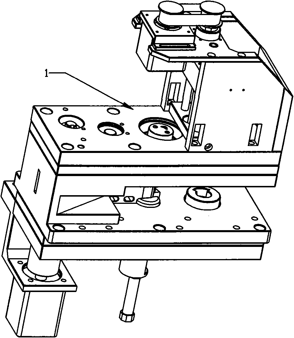
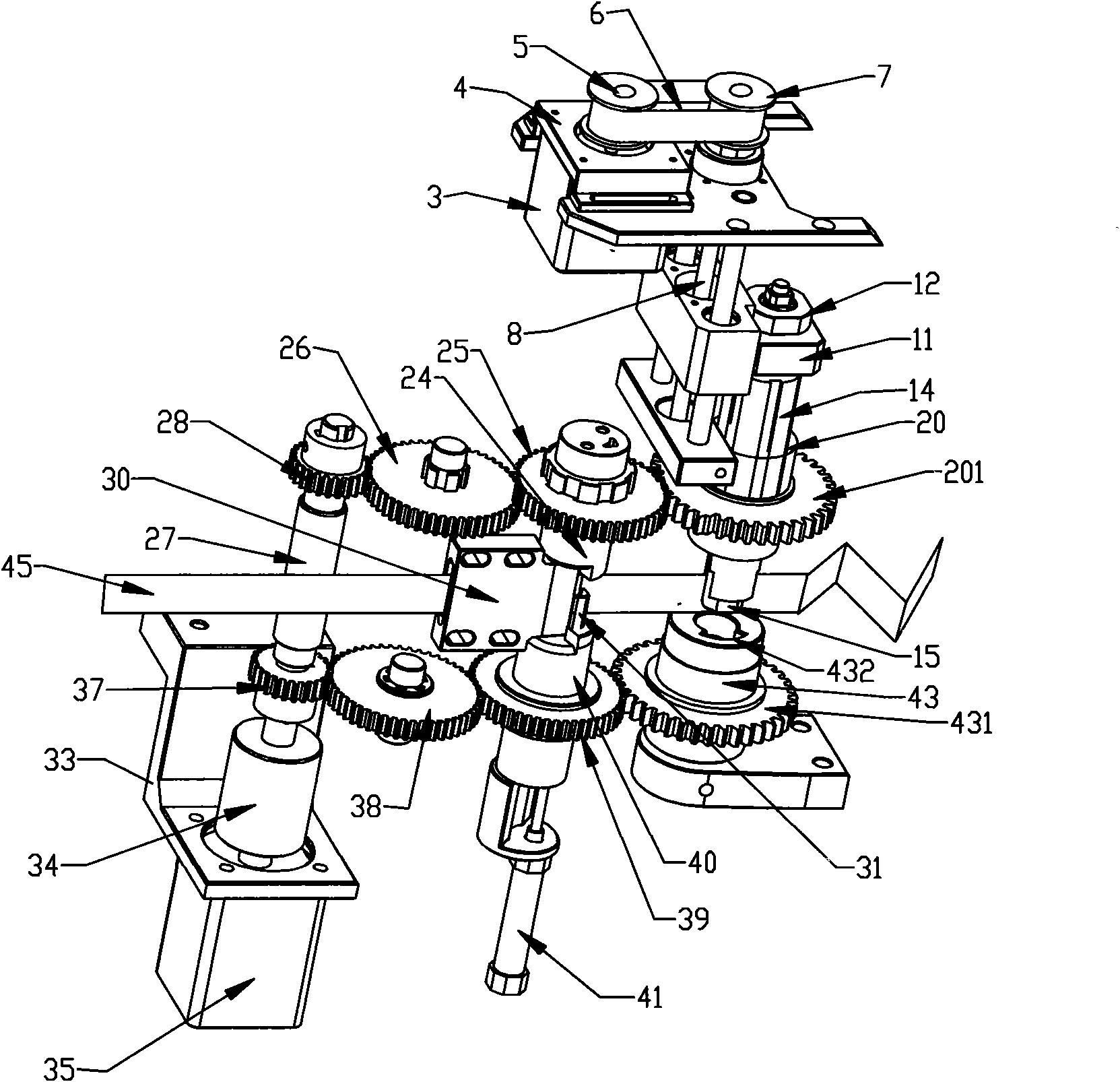
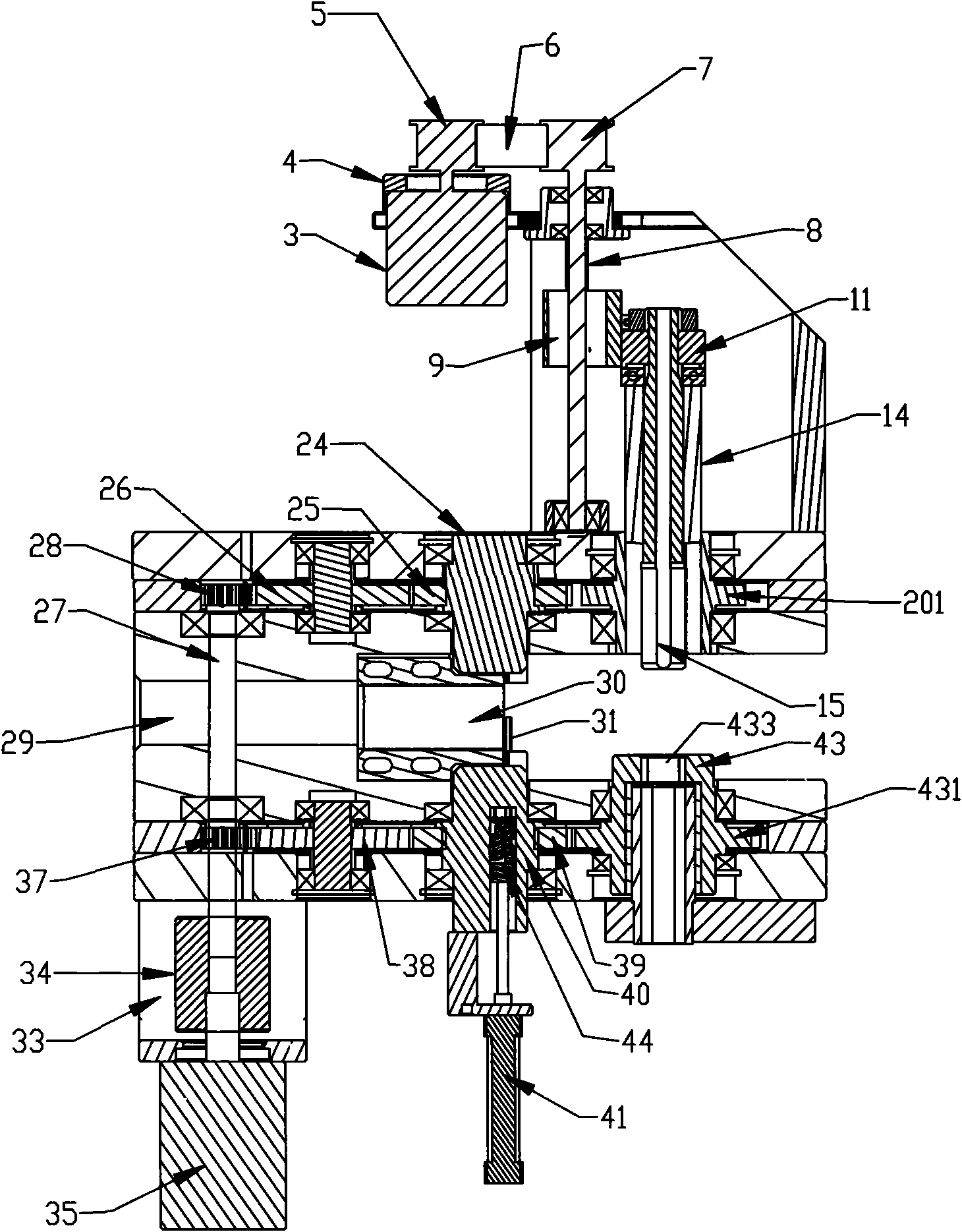
[0026] Such as figure 1 , figure 2 , image 3 As shown, the bending and shearing mechanism includes a machine body 1 on which a bending part and a shearing part are arranged.

[0027] The bending part includes a servo motor 35, a gear transmission mechanism, a bending shaft, a bending inner mold 30, a bending outer mold 31, and a bending outer mold lifting mechanism. The gear transmission mechanism includes a main drive shaft 27, upper and lower main shaft gears 28 and 37 , the upper and lower transmission gears 26 and 38, the upper bending shaft gear 25, the lower bending shaft gear 39, the bending shaft includes the upper bending shaft 24, the lower bending shaft 40, the servo motor 35 is installed on the body 1, and the servo motor is fixed On the seat 33, the upper and lower main shaft gears 28 and 37 are driven by coupling 34 to the main drive shaft 27, and the upper and lower main shaft gears 28 and 37 drive the upper bending shaft gear 25 and the lower bending shaft ...


PUM


Abstract

The invention discloses a bending and shearing mechanism, which comprises a body. A bending part and a shearing part are arranged on the body; the bending part comprises a servo motor, a transmission mechanism, a bending shaft, a bending inner die, a bending outer die and a bending outer die lifting mechanism; the bending inner die is arranged on the body and provided with a slotted hole through which a metal cutter material passes; the bending outer die is arranged on the bending shaft and driven by the bending outer die lifting mechanism to lift to attach the positive or negative surface of the bending inner die; the servo motor drives the bending outer die through the transmission mechanism to attach a notch of the bending inner die to rotate positively and negatively so as to press and fold the metal cutter material; the shearing part comprises a shearing inner die, a shearing outer die and a shearing part lifting mechanism; the shearing inner die and the shearing outer die are driven by the lifting mechanism to lift; the shearing inner die is axially fixed and provided with a slotted hole through which the metal cutter material passes; the shearing outer die is externally sleeved on the shearing inner die and attached to the orifice of the slotted hole; the shearing outer die is connected with a shearing shaft; and the shearing shaft is driven by the servo motor through the transmission of the transmission mechanism to rotate so as to drive the shearing outer die to rotate the metal cutter material.

Description

technical field [0001] The invention relates to a knife die bending and shearing mechanism. Background technique [0002] The main function of the knife bending and shearing mechanism is to bend the straight metal knife material into a knife mold with the same size and shape as the CAD drawing according to the CAD graphics input into the computer, and then cut it off. [0003] At present, the computer scimitar machine seen on the market has a knife mold bending mechanism that is a joint component composed of two bending heads that are symmetrical and the main body is connected together. The blade is inserted in the middle of the two bending heads. The positive and negative angles are formed by driving the bending parts to swing left and right through the rotating shaft. The shearing mechanism uses a cylinder to push a scissor-like mechanism to cut. [0004] In the process of use, people found that the general-purpose bending and shearing mechanism of the automatic computer...

Claims


Application Information

Patent Timeline
Patent Type & Authority Applications(China)
IPC IPC(8): B21D11/00B21D11/22B21D53/64
Inventor 肖述明
Owner 深圳市华正源数控机电设备有限公司
Why Eureka
Try Eureka