Method and corresponding tool for automatically adjusting the screwing speed of a screwing tool on a continuous scale

A screw speed, automatic adjustment technology, applied in the field of tools, can solve the problems of productivity loss, error, torque overshoot, etc.

Inactive Publication Date: 2015-11-25
ETAB GEORRENAULT
View PDF10 Cites 0 Cited by
  • Summary
  • Abstract
  • Description
  • Claims
  • Application Information

AI Technical Summary

Problems solved by technology

[0016] A tool operating in two consecutive phases thus has the disadvantage of causing the above-mentioned phenomenon when the predetermined speed for the fastening phase is too fast, resulting in torque overshoot; or when the predetermined speed for the fastening phase is too slow, loss of productivity
[0017] Also, with these tools, the user has to select the speed of the screwing program, which of course runs the risk of error

Method used


Image

  • Method and corresponding tool for automatically adjusting the screwing speed of a screwing tool on a continuous scale

Examples


Embodiment Construction

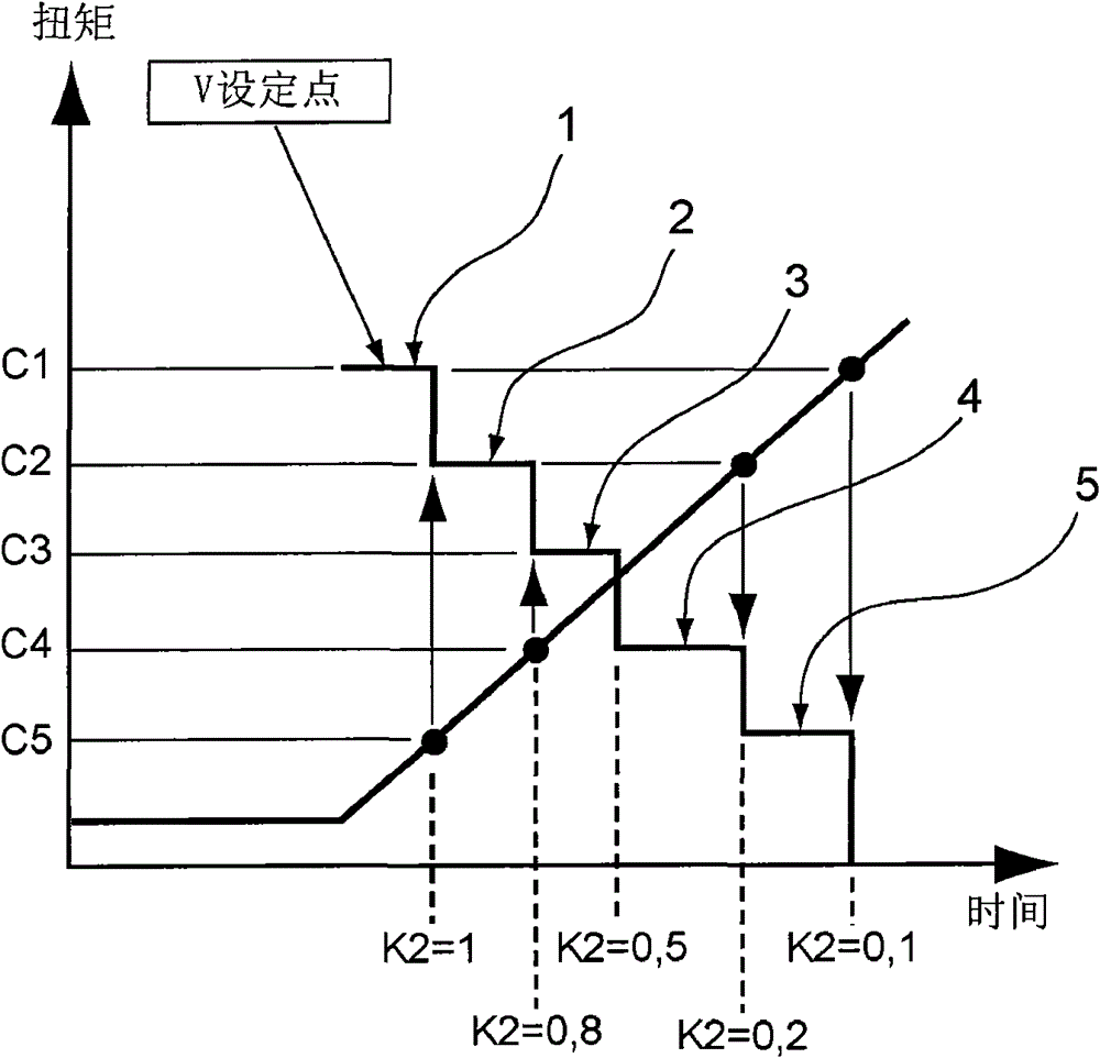
[0056] As indicated above, the principle of the present invention lies in the fact that a method is proposed for automatically adjusting the screwing speed as the torque changes, wherein the screwing speed is determined according to the upper and lower limits of the torque change as a function of time and Adjusted in successive levels defined by the percentage of the final torque to be achieved, where the screwing speed decreases from one level to the next and is calculated based on two coefficients:

[0057] a first coefficient K1, which is determined according to the rate of change dC / dT of the torque or in other words according to the torque change over time;

[0058]A second coefficient K2, which is determined from the torque level achieved (measured) relative to the final torque to be achieved.

[0059] For each level, the setpoint speed Vc is defined as follows:

[0060] Vc=V Max ×K1×K2,

[0061] where V Max = maximum speed of the tool (obtained from the characterist...


PUM


Abstract

The method involves executing two successive stages (1, 2) such that a set point speed is maintained constant for each stage and adjusted from one stage to following stage. The speed is calculated such that the speed is equal to a product of constant coefficient (K1) for a range of torque variations based on time and a constant coefficient (K2) for a range of percentages of final torque. Each stage predefined by lower and upper terminals is expressed in the form of percentage of final torque, where passage of the stage to the following stage modifies a value of the constant coefficient. An independent claim is also included for a screwing tool comprising a locking torque measurement unit.

Description

technical field [0001] The field of the invention is that of tools. More particularly, the present invention relates to industrial tools, and in particular to tools designed to perform screwing with a predetermined torque. Background technique [0002] In the field of the invention, screwing tools are very widely used in the industrial sector and may be stationary (including tools mounted on machines or manipulators) or portable. [0003] These tools may contain electric or pneumatic drive components depending on the intended application. [0004] It is increasingly common that screwing tools used in the industrial field contain components or are to be connected to systems which enable traceability of the operations performed by the tool, providing for example a record of results, such as Final screwing torque, final screwing angle, date and time of operation, or a curve representing the quality (good or bad, according to predetermined parameters) of the screwing performed...

Claims


Application Information

Patent Timeline
Patent Type & Authority Patents(China)
IPC IPC(8): B25B21/00B25B23/14
CPCB25B21/00B23P19/066B25B23/14
Inventor 若斯兰·马里斯热拉尔·派特巴纳尔
Owner ETAB GEORRENAULT
Why Eureka
Try Eureka