Digital optimization control method and system for synchronous rectification of LLC full bridge converter

A full-bridge converter and synchronous rectification technology, applied in control/regulation systems, DC power input conversion to DC power output, instruments, etc., can solve the problems of high power density, LLC circuit efficiency reduction, and circuit power density increase and other problems, to achieve precise off-time adjustment, prevent over-regulation, and improve efficiency

Active Publication Date: 2017-12-01
SOUTHEAST UNIV
View PDF5 Cites 21 Cited by
  • Summary
  • Abstract
  • Description
  • Claims
  • Application Information

AI Technical Summary

Problems solved by technology

②The power density of the whole circuit is further increased
Among them, the current detection technology is more accurate, but the energy loss of the resistance caused by the current detection is quite large, so it will affect the efficiency of the overall topology.
Detecting the drain terminal voltage of synchronous rectifiers has become the only efficient synchronous rectification control scheme. The analog voltage detection technology based on detecting the drain-source voltage of synchronous rectifiers has a very complicated circuit structure, which cannot meet the requirements of high power density. At the same time, This technique can lead to gate parasitic oscillations
The digital detection technology dominated by microcontrollers or FPGAs is currently a better source-drain voltage detection technology. At present, a relatively common synchronous rectification control scheme is mainly to detect whether the body diode of the synchronous rectifier is turned on. In general, the synchronous rectifiers are quickly and adaptively turned off, but this scheme is mainly affected by the switching between diode conduction and reverse conduction, which will reduce the efficiency of the entire LLC circuit, and the corresponding delay problem is at high frequencies. It will be more serious

Method used


Image

  • Digital optimization control method and system for synchronous rectification of LLC full bridge converter
  • Digital optimization control method and system for synchronous rectification of LLC full bridge converter
  • Digital optimization control method and system for synchronous rectification of LLC full bridge converter

Examples


Embodiment Construction

[0033] The technical solution of the invention will be described in detail below in conjunction with the accompanying drawings.

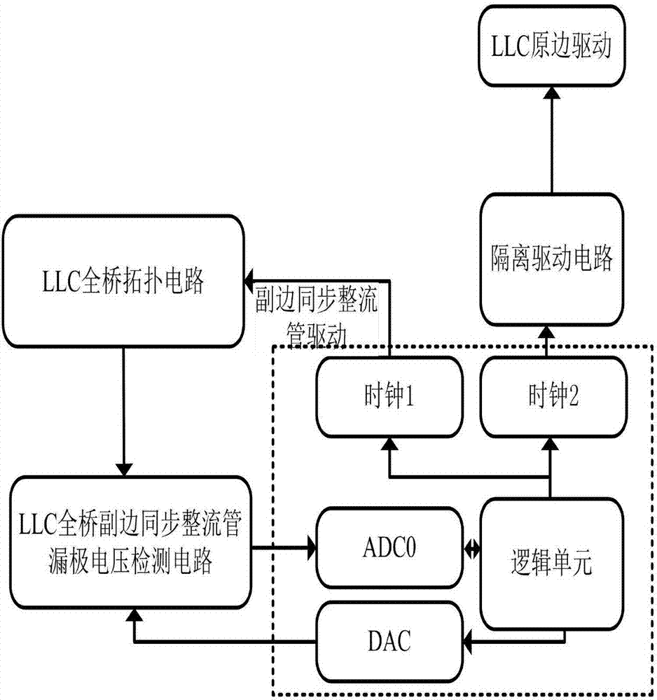
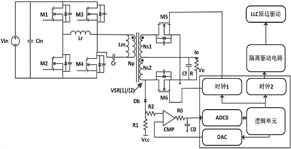
[0034] Such as figure 1 , 2 The control system of the present invention includes a full-bridge LLC topology circuit, a secondary synchronous rectifier drain terminal voltage detection circuit of the full-bridge LLC topology circuit, a control circuit with a microcontroller as the core, and an isolation drive circuit. Among them, the full-bridge LLC topology circuit secondary-side synchronous rectifier drain voltage detection circuit includes a full-bridge LLC topology circuit secondary-side synchronous rectifier drain voltage sampling circuit, a comparator CMP and a resistor R 0 with capacitance C 0 formed filter circuit. The drain terminal voltage sampling circuit of the secondary synchronous rectifier tube of the full-bridge LLC topology circuit includes a resistor R 1 , resistance R 2 and the diode D b , resistor R 1 One end of the resisto...


PUM


Abstract

The invention provides a digital optimization control method and system for synchronous rectification of an LLC full bridge converter. The drain terminal voltage before and after the shut-off of a synchronous rectification tube at the full bridge LLC secondary side is respectively sampled; the twice sampling results are subjected to logic comparison through a comparator; a microcontroller regulates the shot-off time of the synchronous rectification tube at the full bridge LLC secondary side according to the logic comparison result; the precise sampling of the drain terminal voltage before and after the shut-off of the synchronous rectification tube at the full bridge LLC secondary side is realized by using the interruption matching of the microcontroller; the shut-off of the synchronous rectification tube at the full bridge LLC secondary side at the optimum shot-off time is realized through comparing the time command to be regulated given by the microcontroller in real time; and the whole efficiency of the full bridge LLC is improved.

Description

technical field [0001] The invention relates to an LLC resonant full-bridge switching converter adopting a synchronous rectification mode, in particular to a digital optimization control method and system for synchronous rectification of an LLC full-bridge converter. Background technique [0002] At present, the switching frequency in the LLC power converter is getting higher and higher, and the advantages brought by the increase of the switching frequency are as follows: ① The volume of the energy storage device (inductor, transformer, capacitor, etc.) in the circuit is correspondingly reduced. ②The power density of the whole circuit is further increased. However, the increase of switching frequency also brings about the increase of various switching losses and conduction losses, so synchronous rectification is widely used to replace diode rectification, especially in the case of high output current. [0003] At present, there are three types of synchronous rectification c...

Claims


Application Information

Patent Timeline
Patent Type & Authority Applications(China)
IPC IPC(8): H02M3/335
CPCH02M3/33515H02M3/33592Y02B70/10
Inventor 孙伟锋夏熙俞居正朱俊杰钱钦松陆生礼时龙兴
Owner SOUTHEAST UNIV
Why Eureka
Try Eureka