
Intelligent electronic lock

An electronic door lock, intelligent technology, applied in cylinder pin locks, electric alarm locks, electric check locks, etc., can solve the problems of inconvenient installation, use, poor security, and unsuitable for families, and achieve anti-theft performance. High, high anti-theft, wide range of effects

Active Publication Date: 2010-10-20
ZHUHAI WEIMA TECH CO LTD
View PDF4 Cites 28 Cited by
  • Summary
  • Abstract
  • Description
  • Claims
  • Application Information

AI Technical Summary

Problems solved by technology

However, among these electronic locks, the magnetic card and IC card structure are gradually eliminated due to their fragile and weak security; TM cards and radio frequency cards are correspondingly more convenient to use. Among them, these electronic locks are designed to prevent electronic locks from malfunctioning. Or the door is locked after a power failure, and the mechanical lock cylinder is generally retained, but in this way, after the electronic lock is powered off, it becomes an ordinary mechanical lock, which has a large security loophole; Locks generally need to be in the state of power-on fortification for a long time, and the power supply method mainly adopts mains power supply. For home users, it is inconvenient to install and use, especially for families that have been decorated indoors. Therefore, the current electronic The locks are only suitable for guesthouses, hotels, parking lots, public lockers and other occasions where people are on duty or the security is low. They are not suitable for home use, and the China Lock Industry Association also recommends that families use high-performance mechanical anti-theft locks. instead of electronic anti-theft lock

Method used


Image

  • Intelligent electronic lock
  • Intelligent electronic lock
  • Intelligent electronic lock

Examples


Embodiment Construction

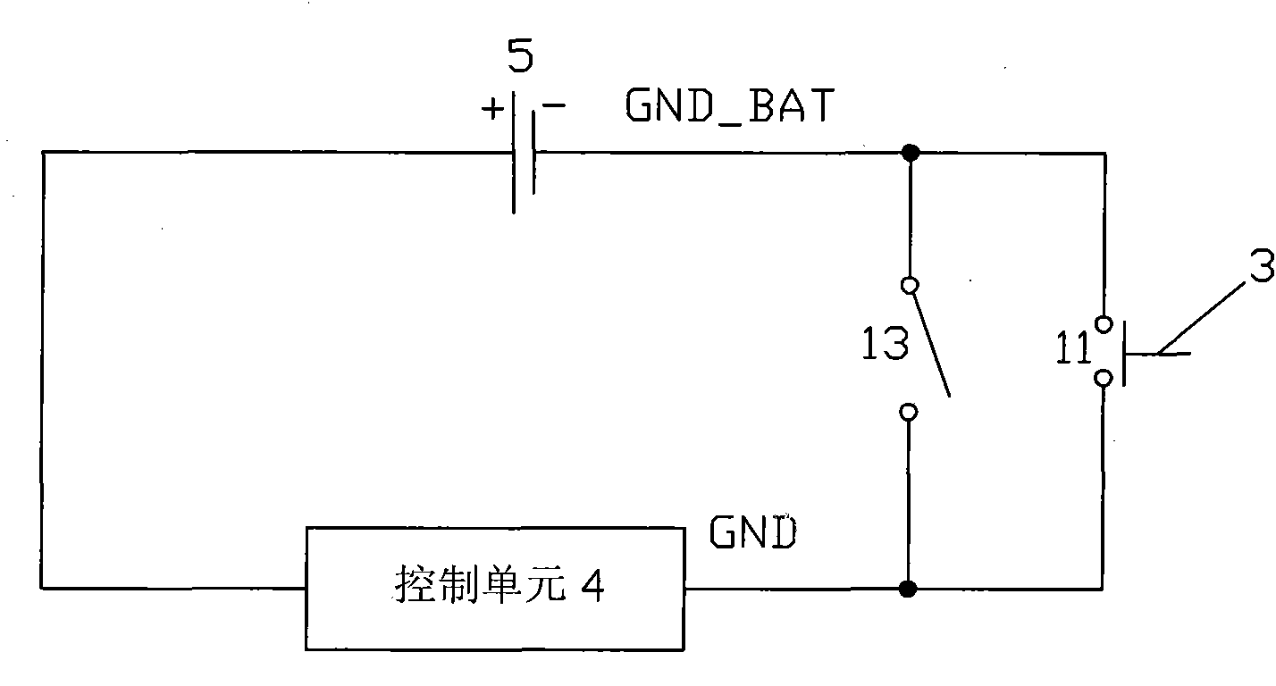
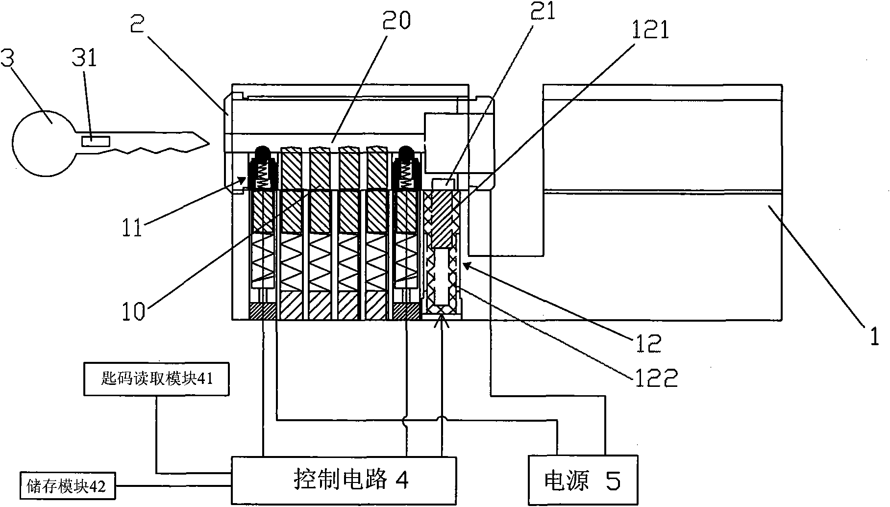
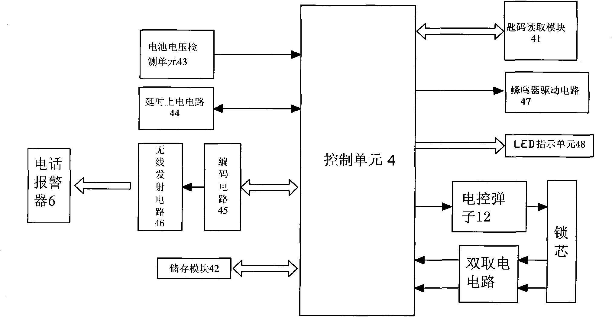
[0020] refer to Figure 1 ~ Figure 3 , an intelligent electronic door lock provided by the present invention can be mainly divided into a mechanical part and an electronic part, wherein the mechanical part is the same as a traditional mechanical lock, including a lock core 1, a lock cylinder 2 and a key 3, and the lock hole of the lock core 1 A mechanical pin 10 is installed inside, and a key hole 20 is provided on the lock cylinder 2. Its working principle is the same as that of a traditional mechanical lock. It is locked through the cooperation of the mechanical pin 10 and the lock cylinder 2, and the key 3 is inserted into the key hole 20 to jack up the mechanical lock. Ball 10, then can rotate lock barrel 2, and then unblank;

[0021] In addition, the electronic part includes a control unit 4, a power supply 5, a key switch 11, and an electronically controlled marble 12, as well as a key code reading module 41 and a storage module 42 connected to the control unit 4, and ca...


PUM


Abstract

The invention provides an intelligent electronic lock. The lock comprises a lock cylinder, a lock bulb, a key, a control unit, a power supply, a key switch and an electric control billiard, wherein a mechanical billiard is arranged in a lockhole of the lock cylinder; the lock bulb is provided with a key hole; the control unit is connected with a key code reading module and a storage module; the electric control billiard is arranged in the lockhole of the lock cylinder; a groove is reserved on the lateral surface of the lock bulb; a digital chip is arranged in the key; and when the key is inserted into the lockhole and the control unit is electrified, the key can unlock the lock normally if codes are the same, and the key cannot unlock the lock if information of codes is different. The lock combines the advantages of a mechanical lock structure and an electronic structure, can ensure low electricity consumption working of the electronic lock by adopting an electrifying mode, can use batteries to supply electricity, and can ensure service life. Therefore, the lock has wide application range, and can be arranged in various houses, buildings and household places conveniently to replace conventional locks. Users can use the lock conveniently without changing existing habits.

Description

technical field [0001] The invention relates to an anti-theft device, in particular to an intelligent electronic door lock. Background technique [0002] With the rapid development of science, technology and economy in our country, people's concept of home has developed from meeting the simple living requirements at first to focusing on the humanized needs of houses, such as a series of security, Comfortable, fast, and convenient living quarters, among which, the safety of the home environment is one of the most important requirements. In addition to human factors, the security of the current community and home environment is also an indispensable and important measure for the setting of the security alarm system. For a long time, people's traditional security measures for houses are mainly realized by installing solid anti-theft iron doors, guardrails and locks with mechanical structures. Ideally, especially without alarm and notification measures for various emergencies,...

Claims


Application Information

Patent Timeline
IPC IPC(8): E05B49/00E05B27/00E05B45/06E05B19/00E05B17/22
Inventor 沈东风
Owner ZHUHAI WEIMA TECH CO LTD
Learn More