Cooling bed driving shaft and manufacturing method thereof

A technology for drive shafts and cooling beds, which is applied in the manufacture of tools, eccentric shafts, welding equipment, etc. It can solve the problems of drive shaft clamping, alignment difficulties, different crank deflection angles, and difficulty in securing crank holes, etc., to save manpower and material resources and processing time, increased welding difficulty, and reduced machining difficulty

Inactive Publication Date: 2010-10-20
TIANJIN SERI MACHINERY EQUIP
View PDF4 Cites 3 Cited by
  • Summary
  • Abstract
  • Description
  • Claims
  • Application Information

AI Technical Summary

Problems solved by technology

[0003] There are two problems with this manufacturing method: (1) When turning the shaft diameter at both ends of the drive shaft as a whole, it is necessary to accurately calculate the counterweight weight and eccentric position of the three cranks
During the process of boring the 3 crank connection holes, it is difficult to clamp and align the drive shaft. The deflection angles of the 3 cranks are different and their interrelationships are complicated. also difficult to guarantee

Method used


Image

  • Cooling bed driving shaft and manufacturing method thereof
  • Cooling bed driving shaft and manufacturing method thereof
  • Cooling bed driving shaft and manufacturing method thereof

Examples


Embodiment Construction

[0026] In order to further understand the invention content, characteristics and effects of the present invention, the following examples are given, and detailed descriptions are as follows in conjunction with the accompanying drawings:

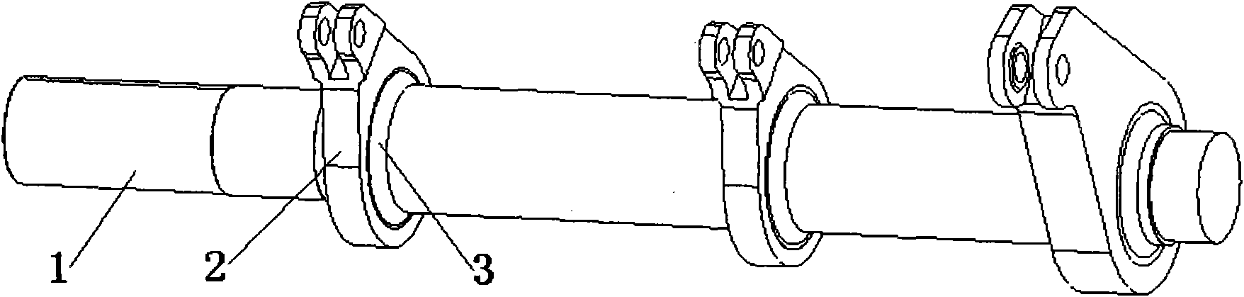
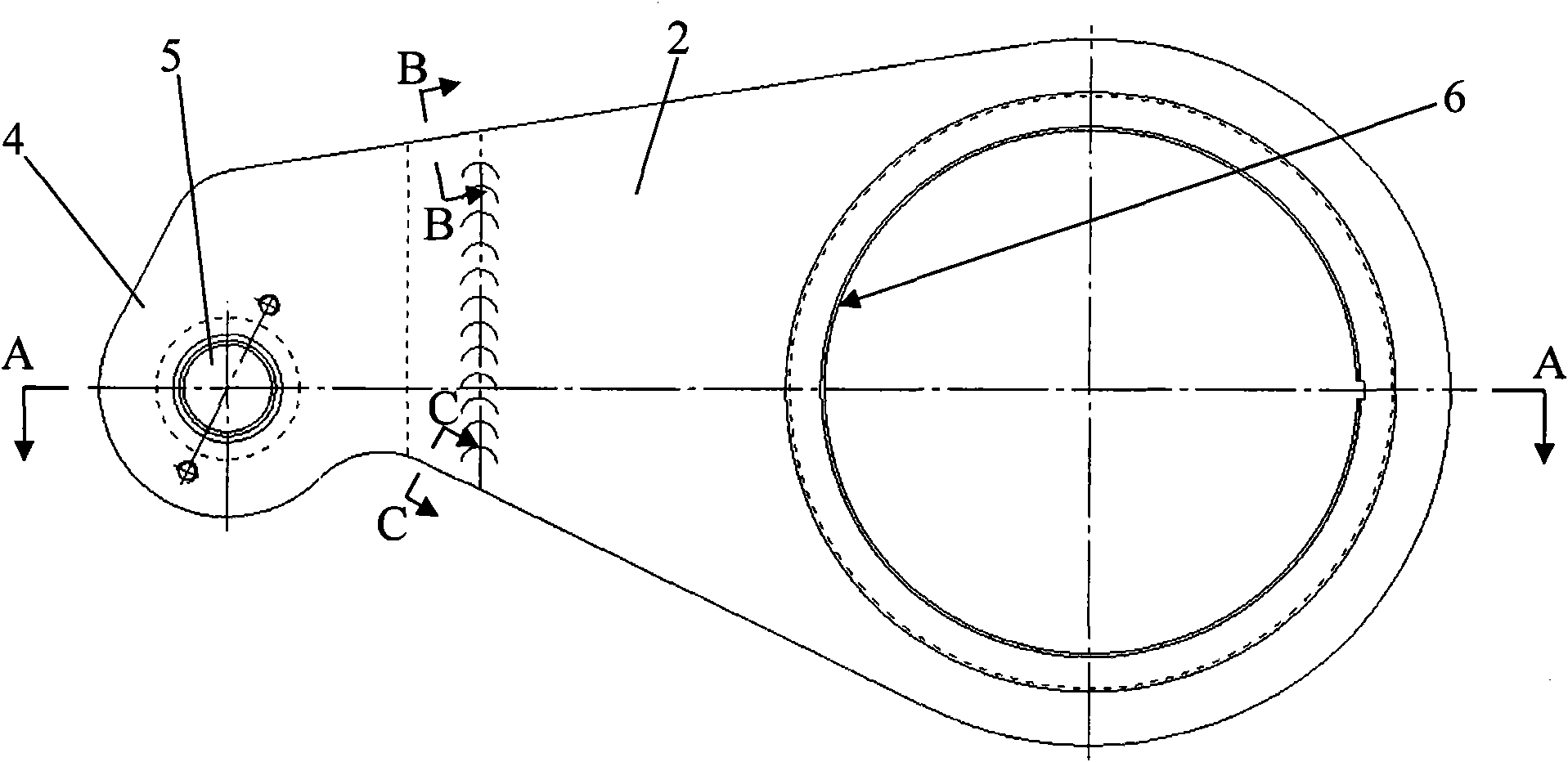
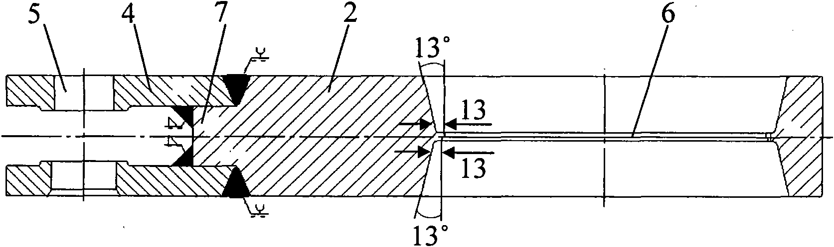
[0027] see Figure 1 to Figure 6 , Shaft 1 is shaped on three pillow blocks 3, each pillow block is welded with a crank 2 with a fork 4 on the head, and a connecting hole 5 is formed on the fork. The crank hole 6 and the pillow block are interference fit (H7 / p6), and the circumferential positioning key of the standard key fit (25JS9 / 25h8) is installed between the crank hole and the pillow block, and the axial positioning key is formed on the pillow block. Shaft shoulder, the fork of the crank is a splicing structure, the splicing structure is that the cross section of the splicing end 7 of the crank and the fork is convex, and the splicing ends of the crank and the fork are respectively shaped with welding grooves. The left and right mating ...


PUM


Abstract

The invention relates to a cooling bed driving shaft and a manufacturing method thereof. The cooling bed driving shaft is characterized in that a crank hole and a pillow block are in interference fit and a circumferential positioning key is arranged between the crank hole and the pillow block; a shaft shoulder axially positioned is arranged on the pillow block; a fork entry of a crank is of a splicing structure; the section of the crank and a splicing end of the fork entry is in the shape of convex; the crank and the splicing end of the fork entry are respectively provided with a welding groove; a complete penetration J welding groove with 13-degree double-edge and 80mm in depth is arranged on a left-right mating surface; the left and right mating surfaces are obtained by welding the crank hole and the pillow block. The manufacturing method is as follows: (1) machining the shaft and the crank respectively into finished products; (2) adopting a hot charging way and assembling the crank hole and the pillow block into a whole through the key and the shaft shoulder; (3) taking counterweight scale mark position on the shaft as reference to combing the counterweight on the shaft; (4) arranging the driving shaft with the combined counterweight on a welding rolling wheel rack; (5) welding symmetrically each crank at two sides of the crank by two welding operators after the welding rolling wheel rack operates normally; and (6) taking down the counterweight after completing the welding, polishing a shaft surface of the driving shaft to be smooth and removing the splashes. The invention has high manufacturing precision and low cost.

Description

technical field [0001] The invention relates to a device for cooling billets, in particular to a driving shaft of a cooling bed. The invention also relates to a manufacturing method of the cooling bed drive shaft. Background technique [0002] The cooling bed is a kind of equipment for cooling billet, the total weight of the equipment is about 600 tons, the length is 55861mm, and the width is 11600mm. Its main components are: translation device, rack, rack bracket. Its working principle is: the translation device slowly drives the steel billet forward by pushing the rack supported by the rack bracket, and after the steel billet cools down, it enters the next manufacturing process. Among them, the drive shaft in the translation device is the larger pendulum drive part in metallurgical equipment. The total weight of the drive shaft is 14 tons, which is welded by the shaft and three cranks. The shaft weight is 11.6 tons, the shaft length is 5675mm, the shaft diameter is φ490...

Claims


Application Information

Patent Timeline
Patent Type & Authority Applications(China)
IPC IPC(8): F16C3/18B23P15/14B23K31/02
Inventor 常涛朱惠王泉祥
Owner TIANJIN SERI MACHINERY EQUIP
Why Eureka
Try Eureka