Fuel cell stack for jointly applying intraplate counter-flow flow field and interpolate counter-flow flow field

A fuel cell stack and countercurrent technology, applied in fuel cells, fuel cell grouping, fuel cell additives, etc., can solve the problems of insufficient countercurrent, large parasitic power, mutual cooperation and mutual support of coolant flow fields, etc. Evenly distributed effect

Active Publication Date: 2010-10-20
STATE GRID CORP OF CHINA +3
View PDF17 Cites 13 Cited by
  • Summary
  • Abstract
  • Description
  • Claims
  • Application Information

AI Technical Summary

Problems solved by technology

There are three main reasons why the traditional reactant flow field cannot meet the requirements: one is that it cannot support the countercurrent flow of the reactant in the plate; the other is that it cannot support the countercurrent flow between the coolant plates; cooperate and support each other
For this reason, literature Electrochem.Commun.9 (2007) 497-503 and J.Power Sources 109 (2002) 469-476 have proposed a reactant flow field with a certain degree of countercurrent properties in the plate, but due to their insufficient counterflow Therefore, it still cannot effectively promote the realization of four uniform distributions, and the large parasitic power caused by the excessive length of the flow channel groove makes it unable to meet the requirements of expanding the battery scale

Method used


Image

  • Fuel cell stack for jointly applying intraplate counter-flow flow field and interpolate counter-flow flow field
  • Fuel cell stack for jointly applying intraplate counter-flow flow field and interpolate counter-flow flow field
  • Fuel cell stack for jointly applying intraplate counter-flow flow field and interpolate counter-flow flow field

Examples


Embodiment Construction

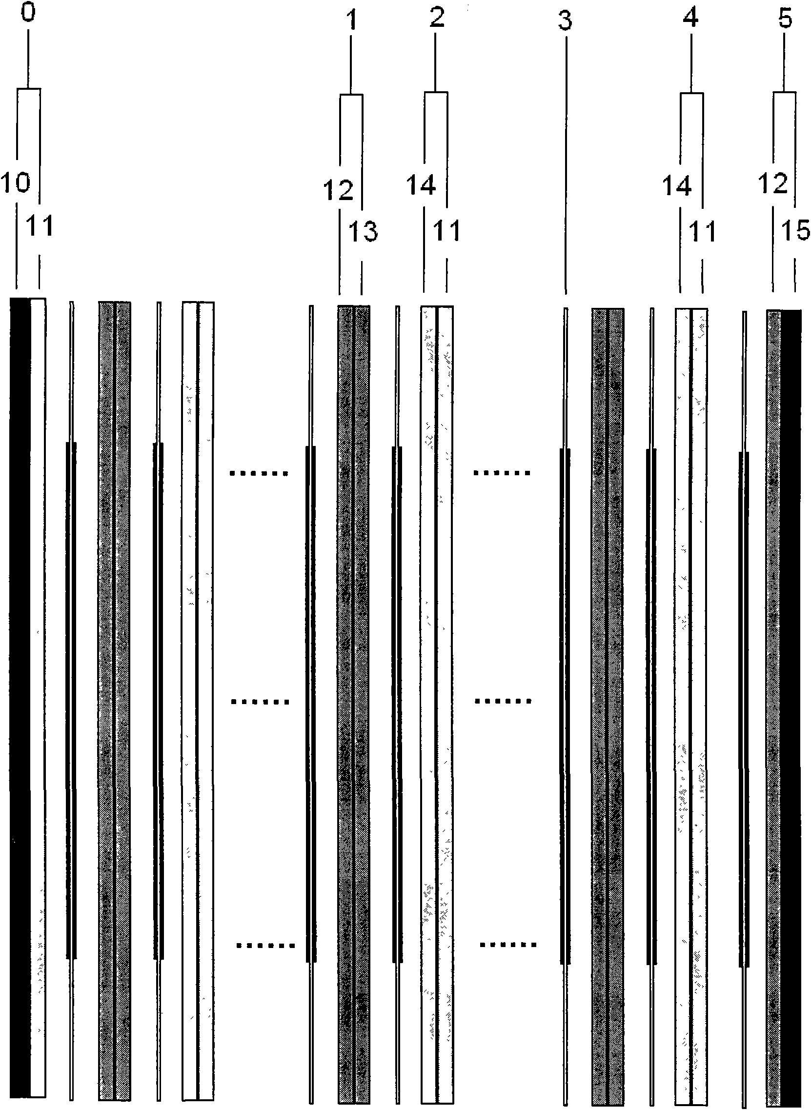
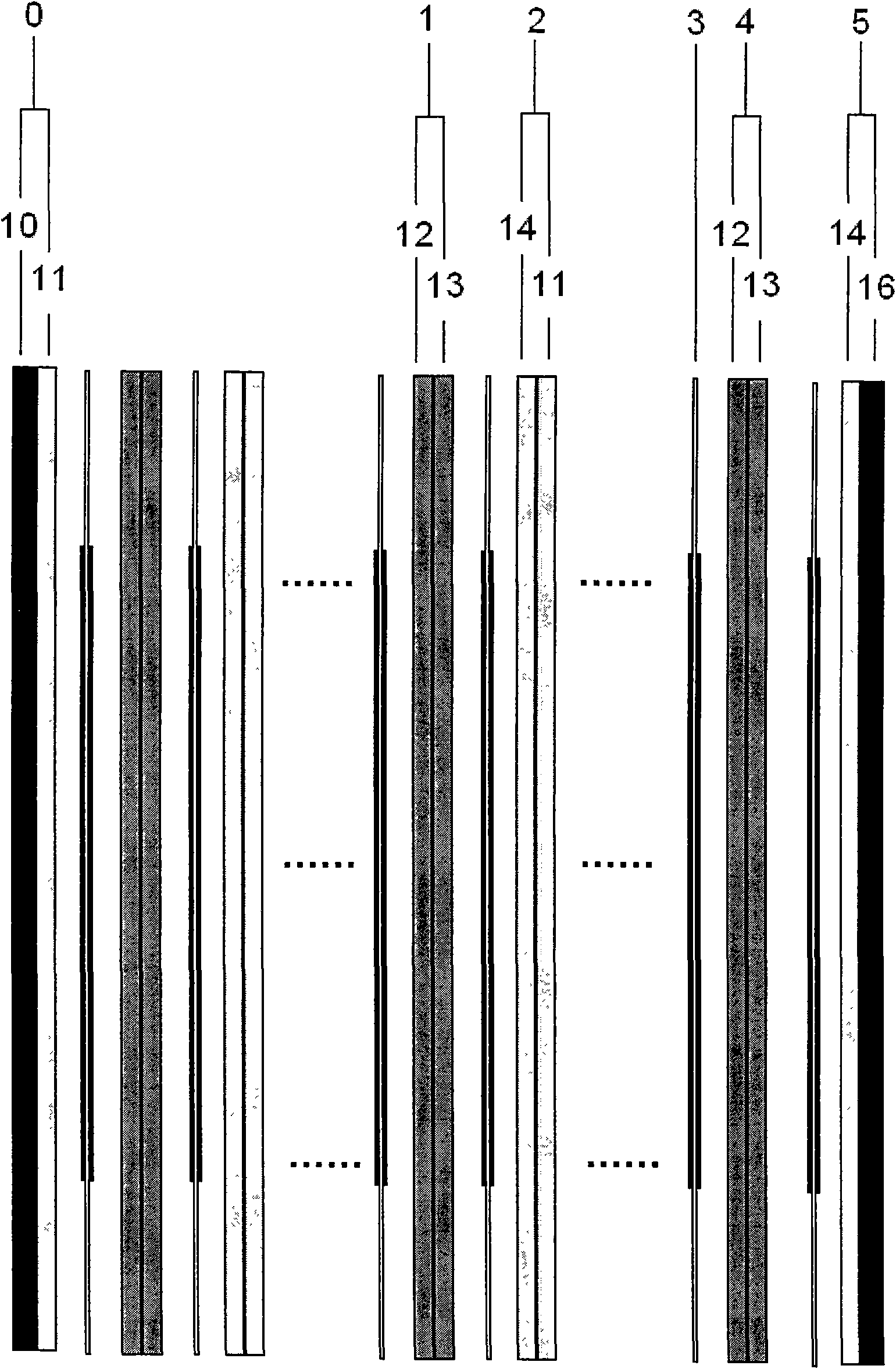
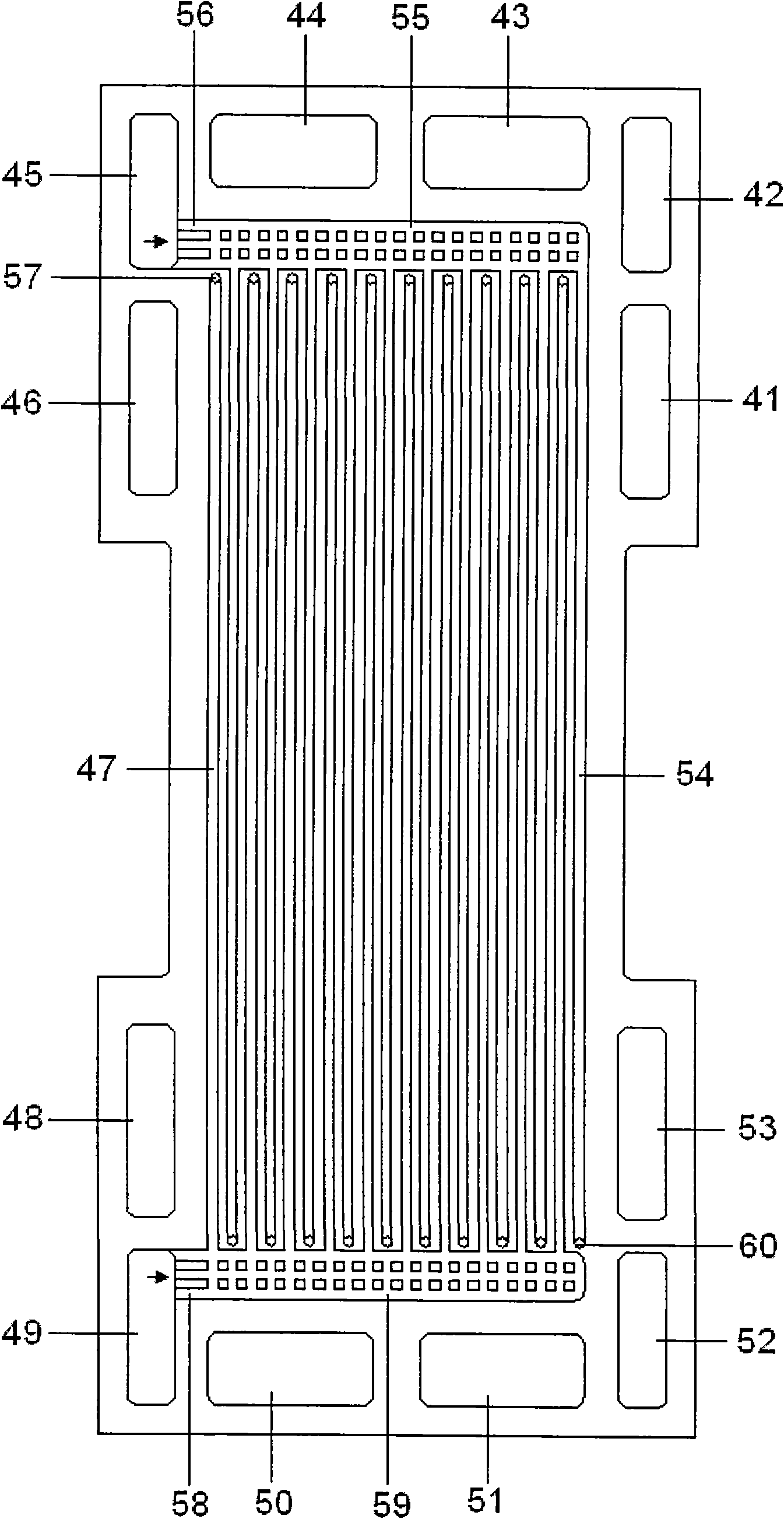
[0031] The present invention proposes a fuel cell stack that combines the countercurrent reactant flow field in the plate and the countercurrent coolant flow field between the plates, such as figure 1 and figure 2As shown, it includes a compound cathode unipolar plate 0 , a plurality of odd bipolar plates 1 , a plurality of even bipolar plates 2 , a plurality of membrane electrodes 3 and a compound anode unipolar plate 5 . The plurality of membrane electrodes 3, the plurality of odd-type bipolar plates 1 and the plurality of even-type bipolar plates 2 are placed between the composite cathode unipolar plate 0 and the composite anode unipolar plate 5, and the two bipolar plates repeat They are arranged alternately, and the composite cathode unipolar plates, multiple odd-shaped bipolar plates, multiple even-shaped bipolar plates and anode composite unipolar plates are connected one by one by membrane electrodes. For two bipolar plates arranged alternately, it is specified that ...


PUM


Abstract

The invention relates to a fuel cell stack for jointly applying an intraplate counter-flow flow field and an interpolate counter-flow flow field, belonging to the technical field of fuel cells. In the cell stack, the two sides of any membrane electrode are respectively provided with an intraplate counter-flow air flow field and an interpolate counter-flow fuel flow field, and the two sides of any membrane electrode are provided with cooling agents which flow to two types of cooling agent flow fields which are just opposite. The air flow field and the fuel flow field cross two relevant surfaces of single-pole plates, and the two types of cooling agent flow fields are respectively embedded at the middle of the back surfaces of the two types of reaction agent flow fields. Two groups of runners of the intraplate counter-flow air flow field, two groups of runners of the counter-flow fuel flow field and two types of cooling agent flow fields of the intraplate counter flow are respectively communicated with two pairs of air inlets and outlets, two pairs of fuel inlets and outlets and two pairs of cooling agent inlets and outlets. The six pairs of inlets are respectively distributed in an opposite angle manner; and in two pairs of inlets and outlets of each type of fluid, the inlet of one pair of inlet and outlet is always adjacent to the outlet of the pair of inlet and outlet. The fuel cell stack has the advantages of simultaneously realizing uniform distribution of four variants such as temperature, concentration, current density and stress and the like.

Description

technical field [0001] The invention relates to a fuel cell stack which combines the countercurrent flow field inside the plate and the countercurrent flow field between the plates, and belongs to the technical field of fuel cells. Background technique [0002] As reported in the literature Int.J.Hydrogen Energy 34 (2009) 6749-6764, the proton exchange membrane fuel cell stack is a highly complex power generation device integrating mass transfer, electricity transfer and heat transfer. In view of the requirements of improving the performance of the battery stack, increasing the life of the battery stack, and improving the adaptability of the battery stack to harsh operating conditions, the species concentration should be as uniform as possible in all active areas of all monolithic cells in the entire battery stack. Four types of uniform distributions are current density uniform distribution, temperature uniform distribution and stress uniform distribution. To achieve the un...

Claims


Application Information

Patent Timeline
Patent Type & Authority Applications(China)
IPC IPC(8): H01M8/10H01M8/02H01M8/04H01M8/24H01M8/0289H01M8/04014H01M8/1004H01M8/2465
CPCY02E60/521Y02E60/50
Inventor 张红飞裴普成张大鹏
Owner STATE GRID CORP OF CHINA
Why Eureka
Try Eureka