

Mapping method of channel measurement pilot frequency and physical resource block
A channel measurement pilot and physical resource block technology, which is applied in the directions of pilot signal allocation, transmission path sub-channel allocation, wireless communication, etc., can solve problems such as undefined CSI-RS mapping, and achieve saving pilot overhead and reducing degradation Effect
- Summary
- Abstract
- Description
- Claims
- Application Information
AI Technical Summary
Problems solved by technology
Method used
Image

Examples
Embodiment 1
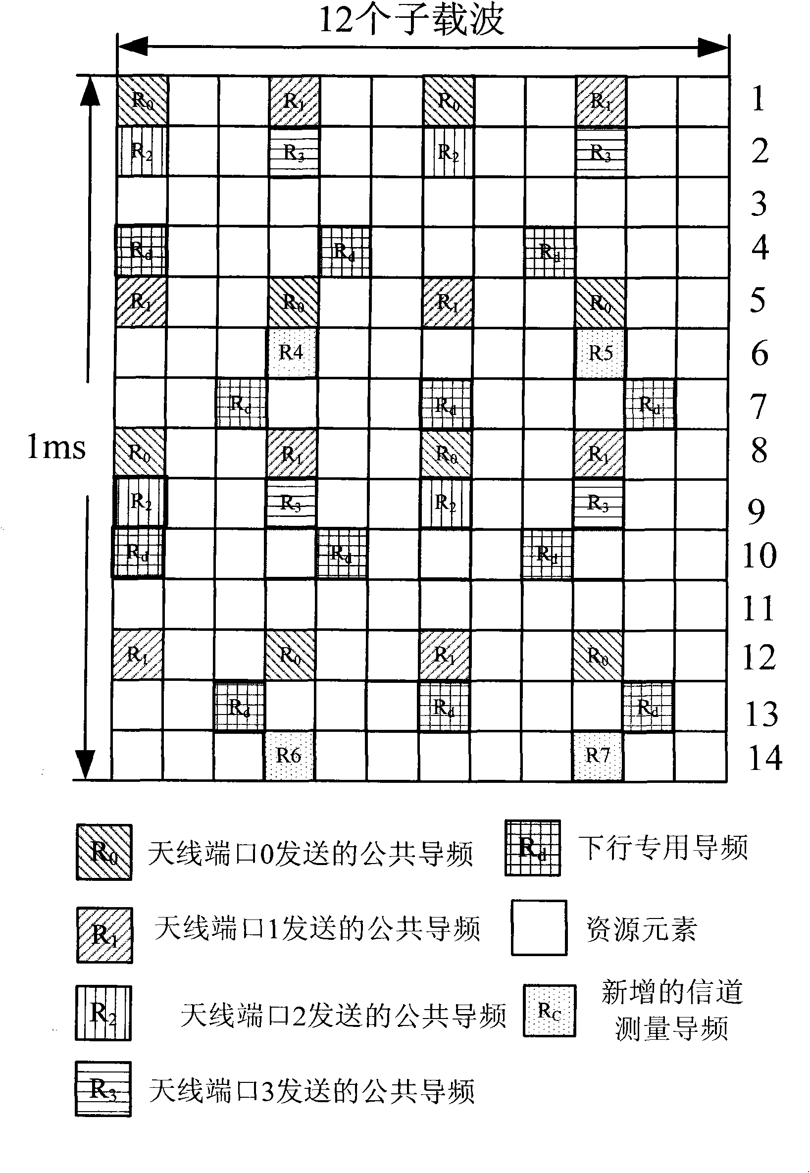
[0062] Such as figure 2 As shown, the base station sets antenna ports 0 to 3 to use the common pilot frequency specified in LTE as the CSI-RS, and the CSI-RS of other antenna ports are mapped in the following manner:
[0063] 1. The CSI-RS of antenna port 4 is mapped to subcarrier 3 of the sixth OFDM symbol of each RB;
[0064] 2. The CSI-RS of antenna port 5 is mapped to subcarrier 9 of the 6th OFDM symbol of each RB;
[0065] 3. The CSI-RS of antenna port 6 is mapped to subcarrier 3 of the 14th OFDM symbol of each RB;
[0066] 4. The CSI-RS of antenna port 7 is mapped to subcarrier 9 of the 14th OFDM symbol of each RB;
[0067] For each subframe configured to be sent by the CSI-RS, the base station maps the CSI-RS to a physical resource block in the manner described above, and sends it out through the antenna port.
[0068] On the full bandwidth, the CSI-RS of each antenna port among antenna ports 4 to 7 is separated by 12 subcarriers.
Embodiment 2
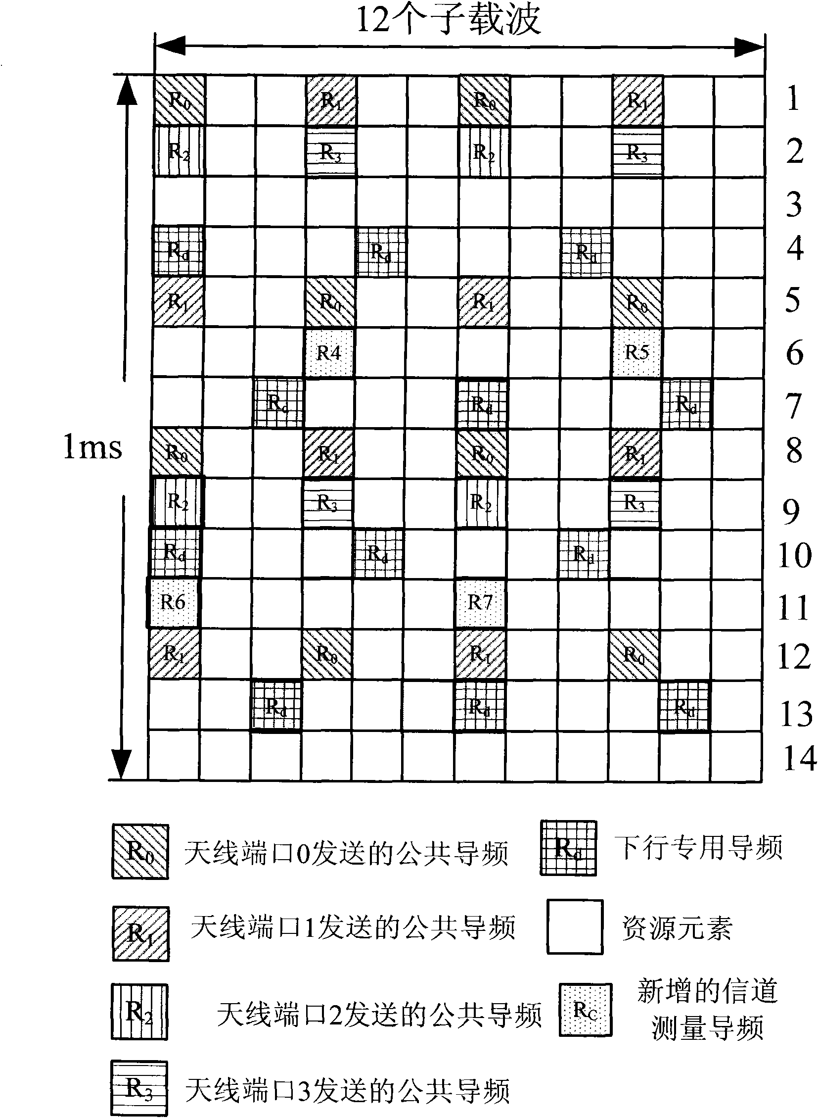
[0070] Such as image 3 As shown, the base station sets antenna ports 0 to 3 to use the common pilot frequency specified in LTE as the CSI-RS, and the CSI-RS of other antenna ports are mapped in the following manner:
[0071] 1. The CSI-RS of antenna port 4 is mapped to subcarrier 3 of the sixth OFDM symbol of each RB;
[0072] 2. The CSI-RS of antenna port 5 is mapped to subcarrier 9 of the 6th OFDM symbol of each RB;
[0073] 3. The CSI-RS of antenna port 6 is mapped to subcarrier 0 of the 11th OFDM symbol of each RB;
[0074] 4. The CSI-RS of antenna port 7 is mapped to subcarrier 6 of the 11th OFDM symbol of each RB (physical resource block);
[0075] For each subframe configured to be sent by the CSI-RS, the base station maps the CSI-RS to a physical resource block in the manner described above, and sends it out through the antenna port.
[0076] On the full bandwidth, the CSI-RS of each antenna port among antenna ports 4 to 7 is separated by 12 subcarriers.
Embodiment 3
[0078] Such as Figure 4 As shown, the base station sets antenna ports 0 to 3 to use the common pilot frequency specified in LTE as the CSI-RS, and the CSI-RS of other antenna ports are mapped in the following manner:
[0079] 1. The CSI-RS of antenna port 4 is mapped to subcarrier 0 of the 6th OFDM symbol of each RB, and subcarrier 6 of the 14th OFDM symbol;
[0080] 2. The CSI-RS of antenna port 5 is mapped to subcarrier 3 of the 6th OFDM symbol and subcarrier 9 of the 14th OFDM symbol in each RB;
[0081] 3. The CSI-RS of antenna port 6 is mapped to subcarrier 6 of the 6th OFDM symbol of each RB, and subcarrier 0 of the 14th OFDM symbol;
[0082] 4. The CSI-RS of antenna port 7 is mapped to subcarrier 9 of the 6th OFDM symbol of each RB, and subcarrier 3 of the 14th OFDM symbol;
[0083] For each subframe configured to be sent by the CSI-RS, the base station maps the CSI-RS to a physical resource block in the manner described above, and sends it out through the antenna po...
PUM
 Abstract
Description
Claims
Application Information